RF tag, RF tag reader, and pulse code key detecting circuit, and RF tag system using them

Inactive Publication Date: 2010-09-30
KITAYOSHI HITOSHI
View PDF4 Cites 26 Cited by
  • Summary
  • Abstract
  • Description
  • Claims
  • Application Information

AI Technical Summary

Benefits of technology

[0035]In addition to a method of easily sending back MPSK modulated sub-carrier signals on the RF tag side, the RF tag system according to the present invention can implement communicat

Problems solved by technology

However, the tag has a drawback of a poor real time responsiveness.
However, although real time responsiveness is excellent, the remote start semi-passive tag has such drawbacks that when the remote start semi-passive tag exists together with a different system (a wireless LAN, a scheduled s

Method used


Image

  • RF tag, RF tag reader, and pulse code key detecting circuit, and RF tag system using them
  • RF tag, RF tag reader, and pulse code key detecting circuit, and RF tag system using them
  • RF tag, RF tag reader, and pulse code key detecting circuit, and RF tag system using them

Examples


Embodiment Construction

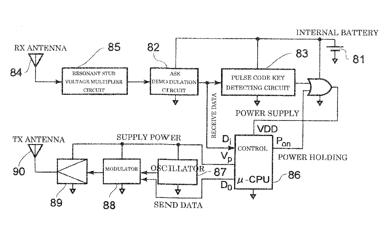
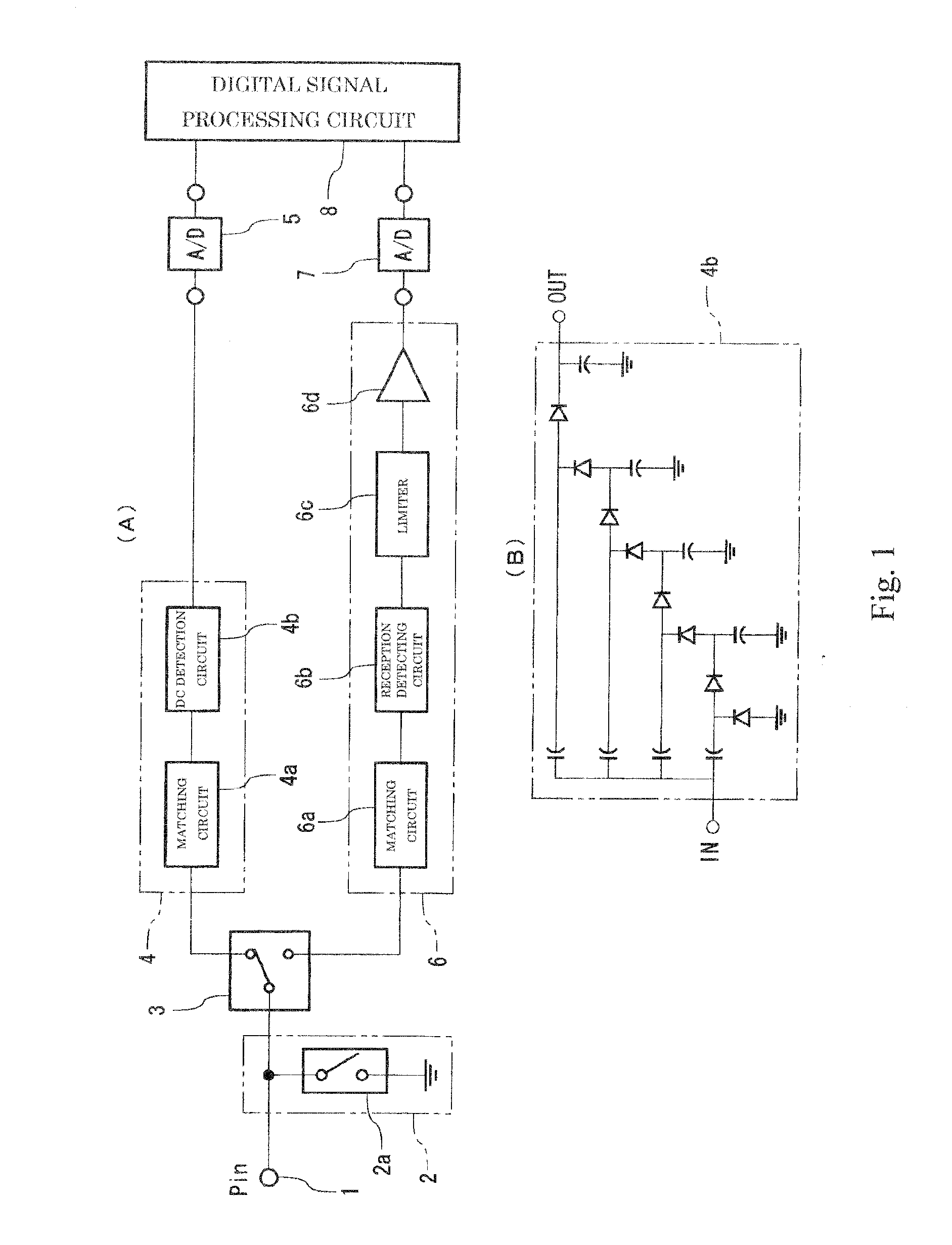
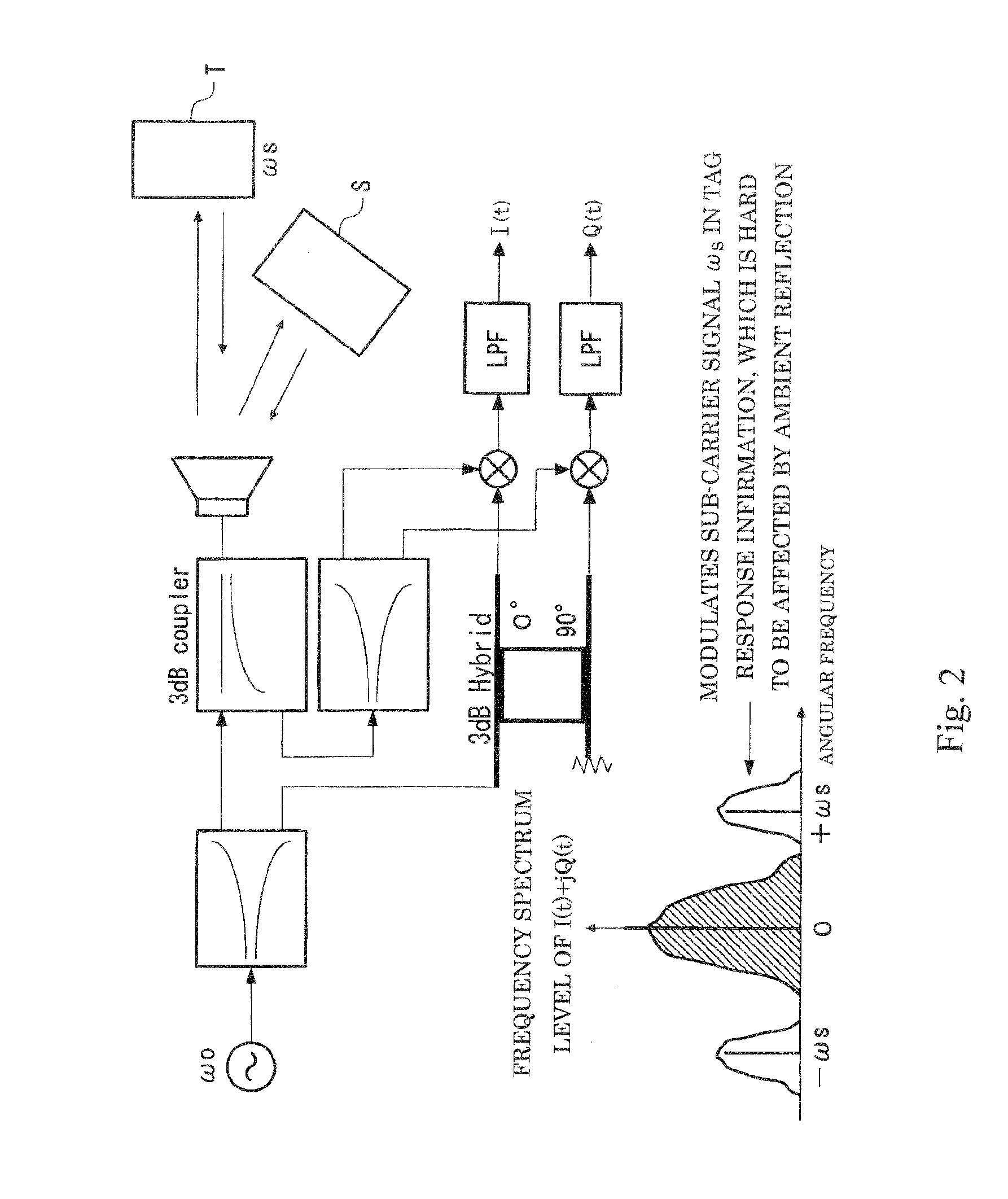
[0118]Next, an RF tag system according to an embodiment of the present invention will be described with reference to the drawings.

[0119]FIG. 3 shows a basic configuration of an RF tag system according to an embodiment of the present invention.

[0120]In the RF tag system, in an environment in which a scheduled start semi-passive RF tag 20 that is suited for long distance communications and has poor real time responsiveness and a remote start semi-passive RF tag 30 that has a relatively short distance for communications and has an excellent real time responsiveness exist together, an RF tag reader 40 is provided, which can read and write both of the RF tags 20 and 30.

[0121]For the RF tag reader 40 in the RF tag system, such an RF tag reader is used, which is a specified low power radio station and is operated in compliance with the ARIB STD-T66 standard (in the 2.45 GHz band, transmission power is 23 dBm, and antenna actual gain is 12 dBi), in which relatively long distance communicati...


PUM


Abstract

An RF tag system is provided, in which in addition to a method of easily sending back MPSK modulated sub-carrier signals on the RF tag side, communication protocols and circuit systems for accurately demodulating modulated waves on the RF tag reader side can be implemented, data transmission from an RF tag to an RF tag reader can be realized over a long operating distance at high speed, and an RF tag can be operated for a long lifetime.

Description

TECHNICAL FIELD[0001]The present invention relates to an RF tag, an RF tag reader, and an RF tag system having the RF tag and the RF tag reader, and particularly to a wireless read / write system combining different types of tags, which allows a scheduled start semi-passive tag and a remote start semi-passive tag to exist together in the same frequency band, and allows tags to operate for a long lifetime at high-speed data transmission.BACKGROUND ART[0002]Patent Document 1: JP 2001-006061 A[0003]Patent Document 2: JP 2005-038037 A[0004]Patent Document 3: Abstract of the 2006 IEICE General Conference (CBS-1-6 UHF Band RF Circuits for RF tag with Battery Supply, March 2006)[0005]In recent years, in order to realize safe, worry-free, convenient society in which everyone is able to connect to computer networks everywhere with users unaware of them in particular based on providing information, search, and integration analysis as ubiquitous networks, ubiquitous services, or the sensor fusio...

Claims


Application Information

Patent Timeline
IPC IPC(8): G08C19/28
CPCG06K19/07749G06K7/10009H04B5/02
Inventor KITAYOSHI, HITOSHI
Owner KITAYOSHI HITOSHI
Why Eureka
Try Eureka