Camera, camera system, and camera body

a camera system and camera body technology, applied in the field of cameras, can solve the problems of inability to accommodate rotational center positions and inaccurate image blur correction, and achieve the effects of reducing size, improving image blur correction performance, and good image blur correction performan

Inactive Publication Date: 2010-09-30
PANASONIC CORP
View PDF11 Cites 49 Cited by
  • Summary
  • Abstract
  • Description
  • Claims
  • Application Information

AI Technical Summary

Benefits of technology

[0018]With an optical or sensor shift system, the optical path of the optical system or the light reception position of the imaging element is changed, so image blur can be corrected while preventing image degradation.
[0053]With this camera body, for example, the operation of the first corrector is controlled on the basis of the first correction amount, and the operation of the second corrector is controlled on the basis of the second correction amount. Accordingly, compared to when image blur correction is performed by just the first or the second corrector, the amount of correction is dispersed among the two correctors, which means that the first and second correction amounts can each be kept small. Consequently, the size of this camera body can be reduced while ensuring good image blur correction performance.

Problems solved by technology

In this case, the calculated amount by which the correcting lens needs to be driven will differ from the drive amount that is actually required, so there is the risk that image blur cannot be corrected accurately.
With this camera, however, it is a premise that the rotational center is disposed along the optical axis, so various rotational center positions cannot be accommodated.

Method used


Image

  • Camera, camera system, and camera body
  • Camera, camera system, and camera body
  • Camera, camera system, and camera body

Examples


second embodiment

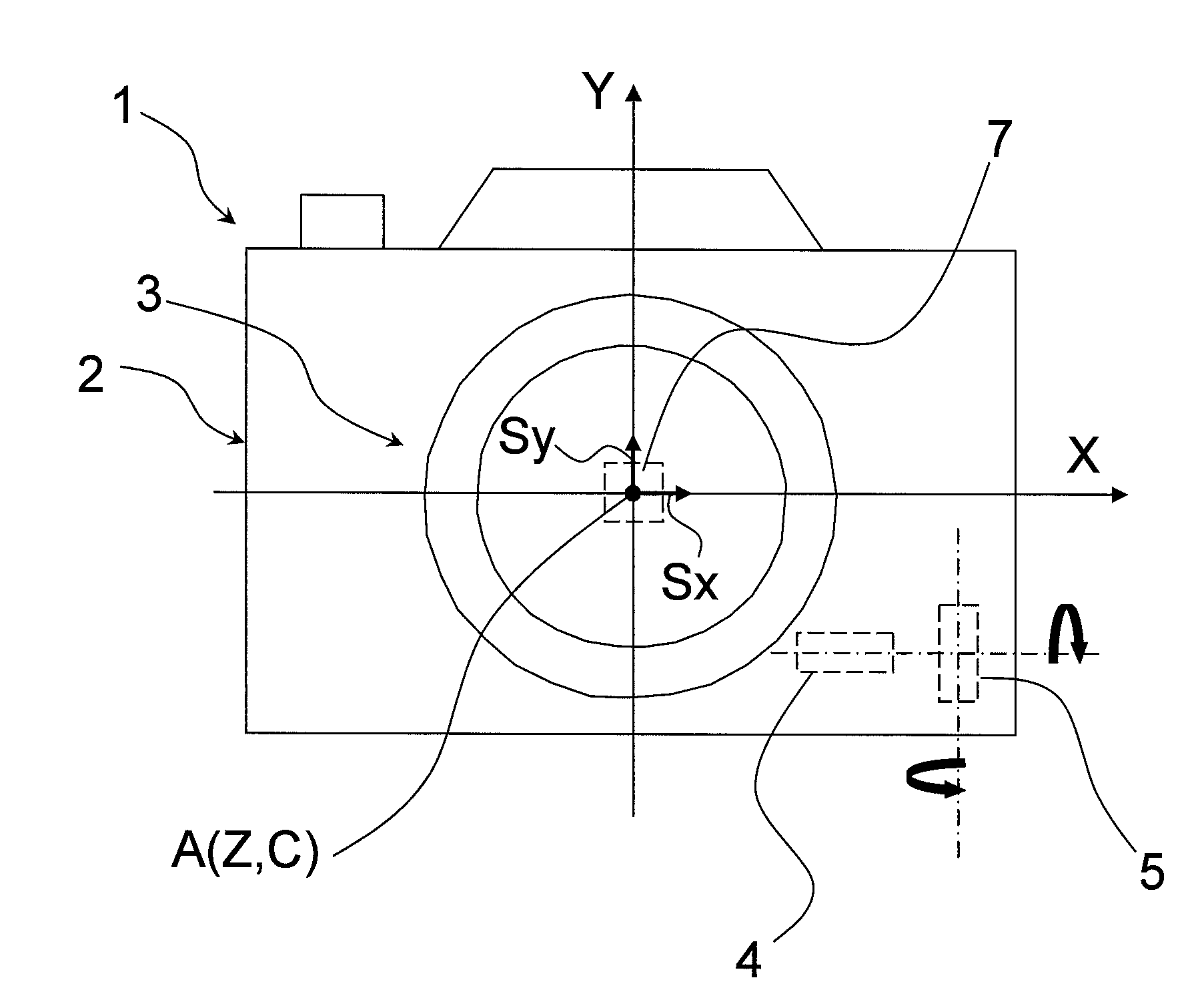
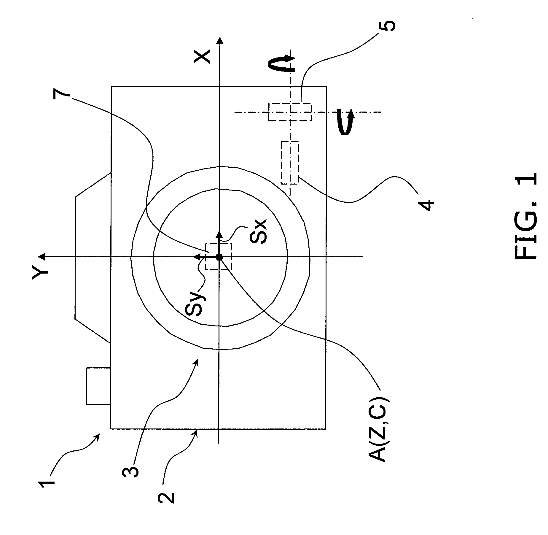
[0258]In the above embodiment, the correcting lens 9 was driven by the first drive unit 10 and the second drive unit 12 on the basis of the drive amount Δd of the correcting lens 9.

[0259]However, for example, the rotational components Δx2 and Δy2 of rotational shake may be corrected by drive of the correcting lens 9, and the shake amounts Δx1, Δy1, and Δz1 caused by remaining translation may be corrected by moving the imaging element 17 in a direction perpendicular to the optical axis A. Specifically, the optical image blur correction apparatus and the sensor shift type of image blur correction apparatus are controlled separately in this embodiment.

[0260]Those components that are substantially the same as in the above embodiment will be numbered the same, and will not described again.

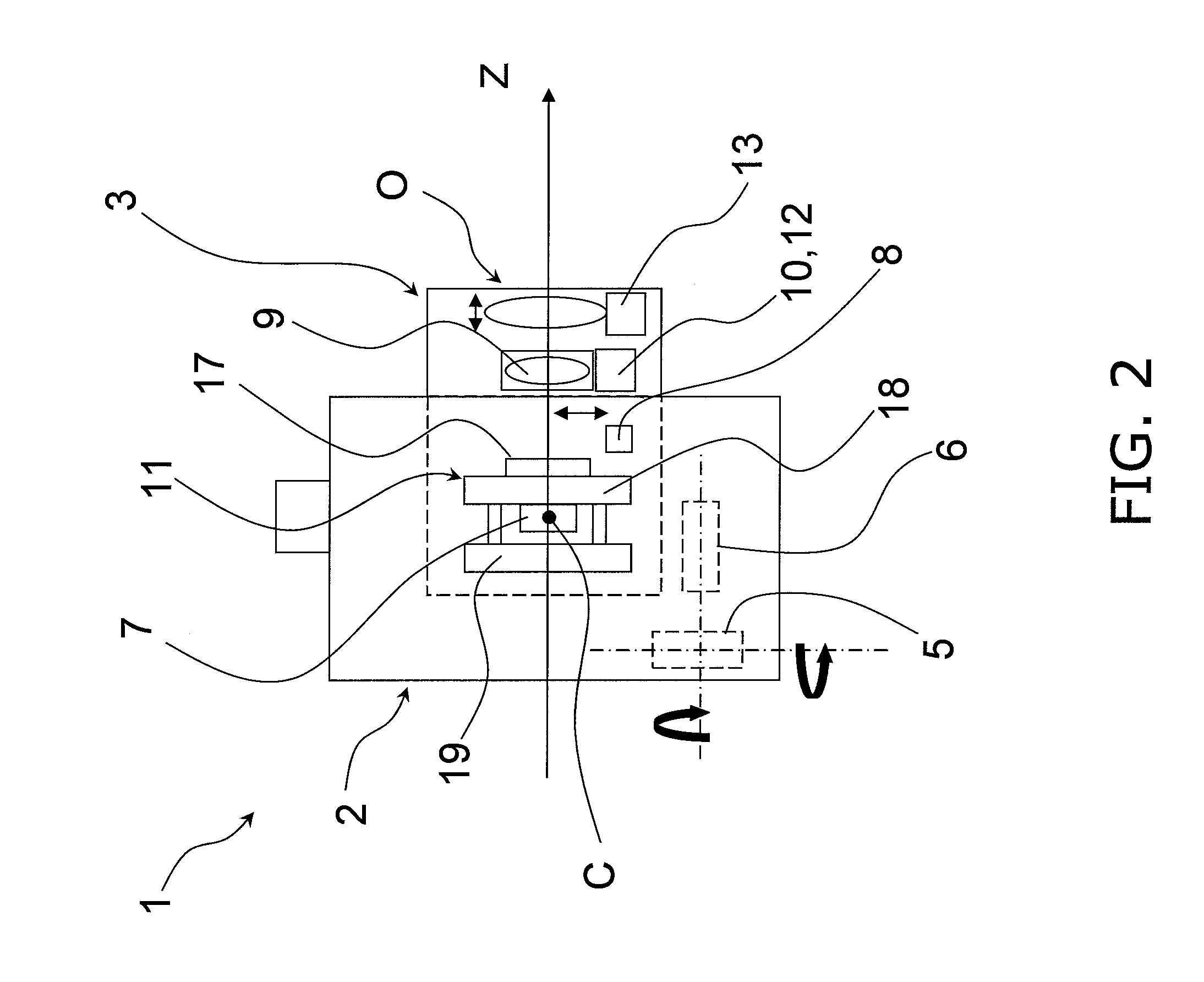
[0261]As shown in FIGS. 30 and 31, this camera 201 has a sensor drive unit 240 (an example of an imaging element driver) that drives the imaging element 17 in two directions perpendicular to the optical...


PUM


Abstract

A camera is provided with which a small size can be achieved while ensuring good image blur correction performance. The camera (1) has an optical system (O), a housing (2), a second drive unit (12) serving as part of an image blur corrector, an imaging element (17), a first angular velocity sensor (4), an acceleration sensor (7), a sensor drive unit (240), and a drive controller (22). The first angular velocity sensor (4) is configured to acquire the rotational angle of the housing (2). The acceleration sensor (7) is configured to acquire the amount of displacement of the housing (2). A correction computer (21) calculates the amount of drive of a correcting lens (9) from the displacement amount acquired by the acceleration sensor (7), and calculates the amount of drive of the correcting lens (9) from the rotational angle acquired by the first angular velocity sensor (4) using the position of the acceleration sensor (7) as a reference. The drive controller (22) controls the operation of the second drive unit (12) on the basis of these drive amounts.

Description

TECHNICAL FIELD[0001]The present invention relates to a camera having an image blur correction function.BACKGROUND ART[0002]A camera having an image blur correction function in order to suppress the image degradation caused by shaking of the camera (hereinafter also referred to as image blur) was known in the past. Such a camera had an image blur correction unit for driving a correcting lens, a shake detection sensor for detecting shaking of the camera, and a correction controller for controlling the operation of the image blur correction unit according to the output of the shake detection sensor. With this camera, the correcting lens is driven by the image blur correction unit on the basis of the amount of shake detected by the image blur detection sensor, so as to cancel out the image blur caused by this shaking, which means that it is possible to acquire images in which image blur is corrected.[0003]More specifically, with a conventional camera, the X and Y axes, which are perpen...

Claims


Application Information

Patent Timeline
Patent Type & Authority Applications(United States)
IPC IPC(8): H04N5/228
CPCG03B5/00H04N5/2328H04N5/23258H04N5/23248H04N23/68H04N23/685H04N23/6812
Inventor HASHI, HIDEYUKIHAYASHI, KENICHIHONSHO, HIRONORITANAKA, MASANOBUSIBUKAWA, KAZUO
Owner PANASONIC CORP
Why Eureka
Try Eureka