
Image communication apparatus, control method thereof, and storage medium

Inactive Publication Date: 2010-09-30
CANON KK
View PDF2 Cites 6 Cited by
  • Summary
  • Abstract
  • Description
  • Claims
  • Application Information

AI Technical Summary

Benefits of technology

[0017]With the present invention, it is possible to transmit input image data

Problems solved by technology

With the confidential communication, however, a problem is posed that a sender user is unable to confirm whether image data has been actually sent to the recipient.
Thus, the receiver apparatus must keep storing the image data transmitted through confidential transmission until the recipient logs in the receiver apparatus and the image data is output, and therefore, there is a fear that the memory of the receiver apparatus is occupied for a long time.
However, even if presence information is used as in Japanese Laid-open Patent Publication No. 2005-318503, the following problem can be caused.
Specifically, if the intended user has not logged in the destination terminal when the sender apparatus user attempts to transmit image data, the sender apparatus user has to wait until the recipient logs in the destination terminal or has to prompt by telephone, mail, or the like the recipient to log in the destination terminal, which provides extremely low usability for the sender apparatus user.

Method used


Image

  • Image communication apparatus, control method thereof, and storage medium
  • Image communication apparatus, control method thereof, and storage medium
  • Image communication apparatus, control method thereof, and storage medium

Examples


first embodiment

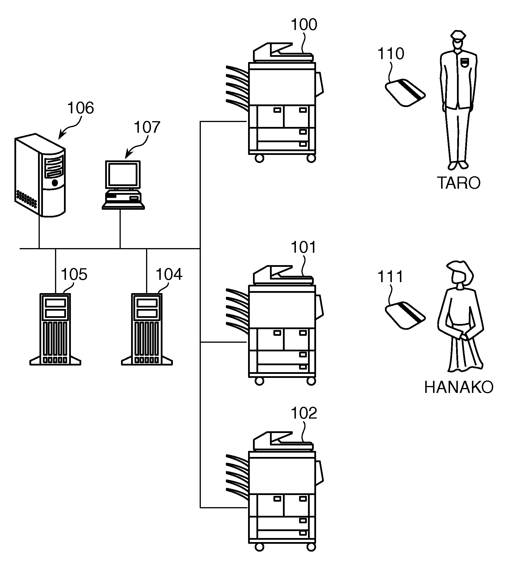
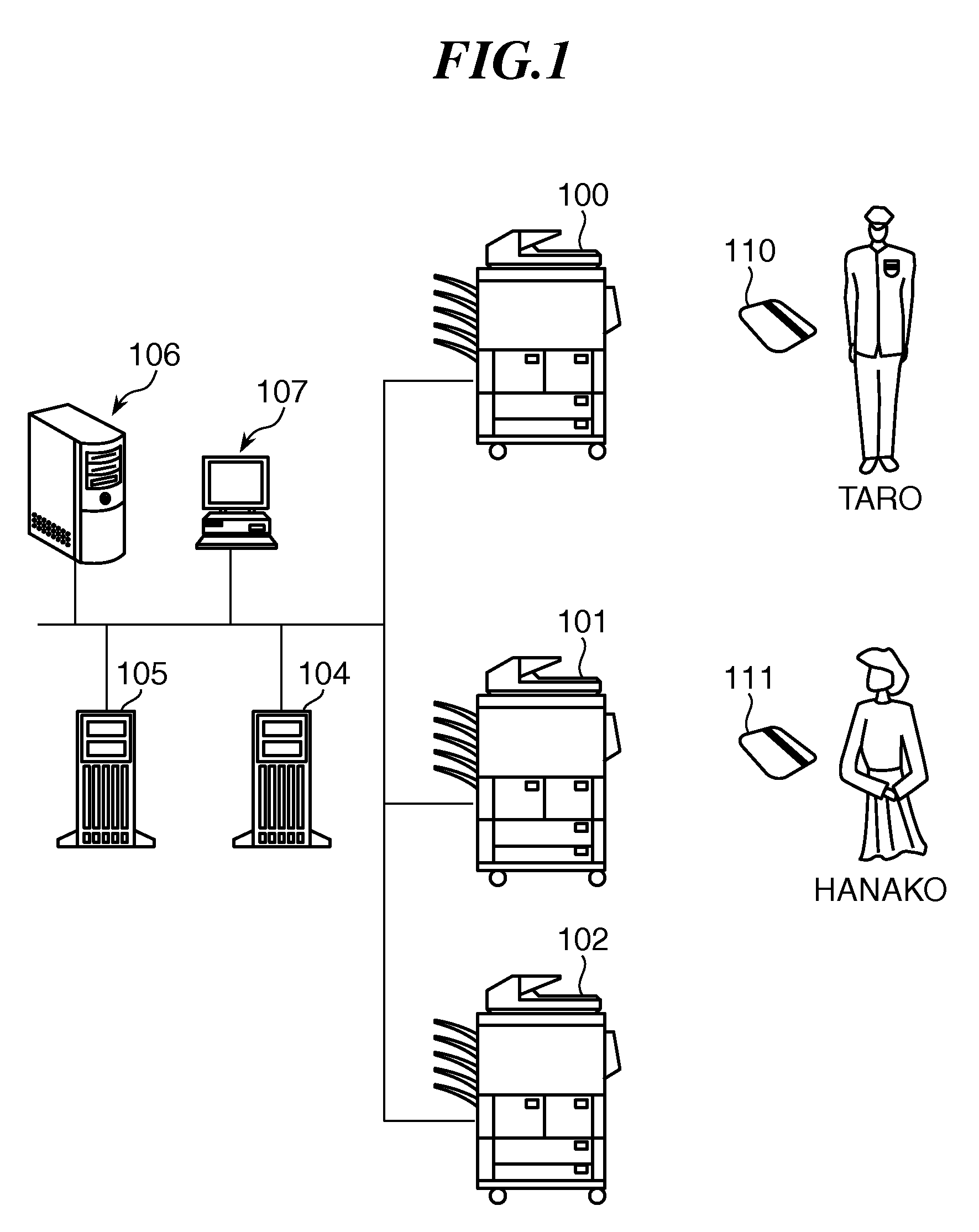
[0038]FIG. 1 schematically shows an image communication system according to this invention. The image communication system is comprised of MFPs 100, 101, 102, a SIP server 104, a presence server 105, a mail server 106, and a mail client 107, which are connected to one another via a network.

[0039]The MFPs 100, 101, and 102, which are an example of image communication apparatuses, are multi-function copying machines each including a scanner and a printer and having, e.g., a copying function and a printer function for printing data created by a computer.

[0040]The SIP server 104 is a server that performs call control for communication under a SIP (session initiation protocol) stipulated in, e.g., RFC 2543. The presence server 105 as a management server that manages users' log-in states in the MFPs 100 to 102 has a presence function (attendance management), an instant message function, and a function of an expanded SIP protocol called SIMPLE (session initiation protocol for instant messa...

second embodiment

[0136]In the following, a description is given of this invention.

[0137]FIGS. 10A and 10B each show an IP-FAX destination setting screen (address book screen) for designating a transmission destination for IP-FAX communication stipulated by ITU-T.38, the setting screen being displayed on the LCD display panel of the operation unit 133 of, e.g., the MFP 100

[0138]When a transmission destination input field 700 is selected, a soft keyboard for inputting a transmission destination is displayed. For the communication using SIP protocol, a transmission destination is designated by SIP destination information. To this end, a destination of sip:mfp102@abc.co.jp is input to the field 700 in FIG. 10A, and a destination of sip:hanako@abc.co.jp is input to the field 700 in FIG. 10B.

[0139]If an equipment address is input to the transmission destination input field 700, a check button 701 is set ON. If a user address is input to the field 700, a check button 702 is set ON. These buttons 701, 702 a...


PUM


Abstract

An image communication apparatus that transmits input image data when detecting that a designated recipient has logged in an external apparatus. An MFP as an image communication apparatus includes a scanner for inputting image data and an operation unit for designating a recipient by whom the input image data should be received. When it is detected that the designated recipient has logged in another MFP which is a transmission destination of the input image data, the input image data is transmitted to the transmission destination MFP.

Description

BACKGROUND OF THE INVENTION[0001]1. Field of the Invention[0002]The present invention relates to an image communication apparatus for transmitting input image data, a control method of the image communication apparatus, and a storage medium.[0003]2. Description of the Related Art[0004]Conventionally, confidential communication has been known as a method for reliably sending confidential image data to a recipient without causing information leakage. In the confidential communication, a sender apparatus transmits image data after designating a storage area corresponding to a recipient. A receiver apparatus stores received image data in the designated storage area and outputs the image data on condition that a user corresponding to the storage area has logged in the receiver apparatus (i.e., if the user has been authenticated).[0005]With the confidential communication, however, a problem is posed that a sender user is unable to confirm whether image data has been actually sent to the r...

Claims


Application Information

Patent Timeline
IPC IPC(8): G06F15/00
CPCG03G2215/00113G03G15/5087G03G2215/00109G03G15/502
Inventor TONEGAWA, NOBUYUKI
Owner CANON KK
Learn More