
Natural Lighting System With Sequential Scanning Process

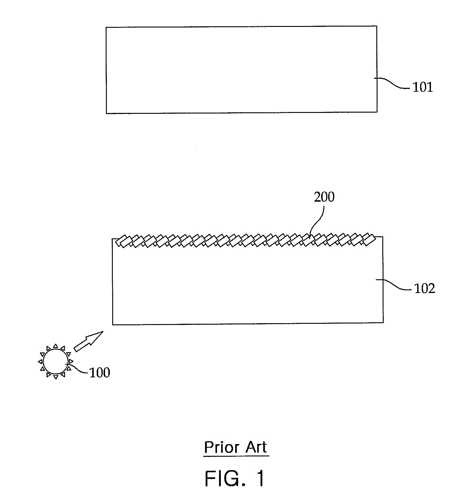
a scanning process and natural lighting technology, applied in lighting and heating equipment, instruments, using daylight, etc., can solve the problem of restricted size of magnified area, and achieve the effect of reducing spatial restrictions, simple system, and reducing installed number

Inactive Publication Date: 2010-09-30
KIM SEUNG HAN
View PDF2 Cites 4 Cited by
  • Summary
  • Abstract
  • Description
  • Claims
  • Application Information

AI Technical Summary

Benefits of technology

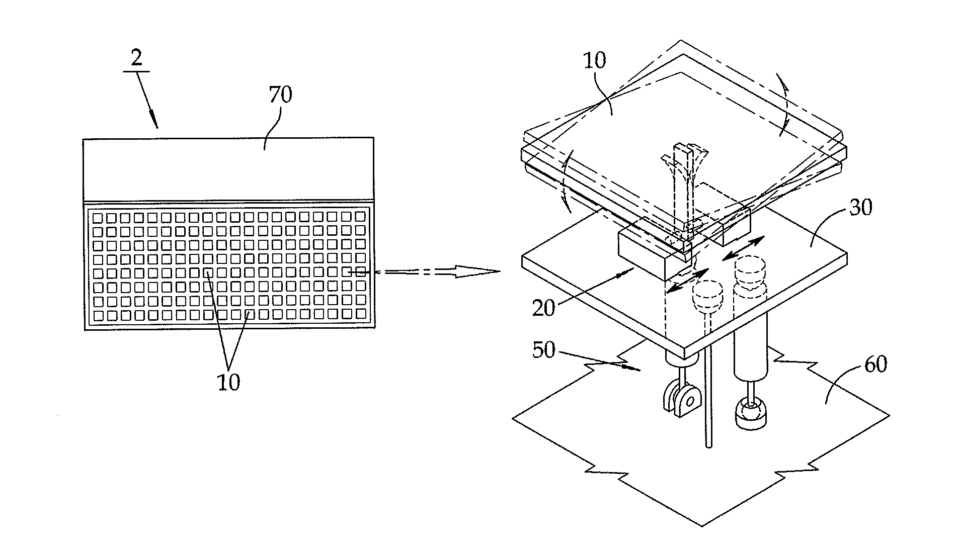
[0020]According to embodiments of the present invention, the natural lighting system sequentially scans the light reflected to the target scanning area by the reflector, thereby enabling a person to feel the reflected light as continuous light through positive afterimage reaction. Further, the natural lighting system can greatly reduce an installed number as compared to an existing natural lighting system, and remarkably reduce spatial restrictions associated with installation. In addition, the natural lighting system establishes a comparatively simpler system as compared to a conventional natural lighting system, and thus can promote convenience of use and fabrication.

Problems solved by technology

However, the size of the magnified area is restricted because the light which a human being feels has to maintain proper sensitivity.

Method used


Image

  • Natural Lighting System With Sequential Scanning Process
  • Natural Lighting System With Sequential Scanning Process
  • Natural Lighting System With Sequential Scanning Process

Examples


Embodiment Construction

[0041]Reference will now be made in detail to exemplary embodiments of the invention with reference to the accompanying drawings.

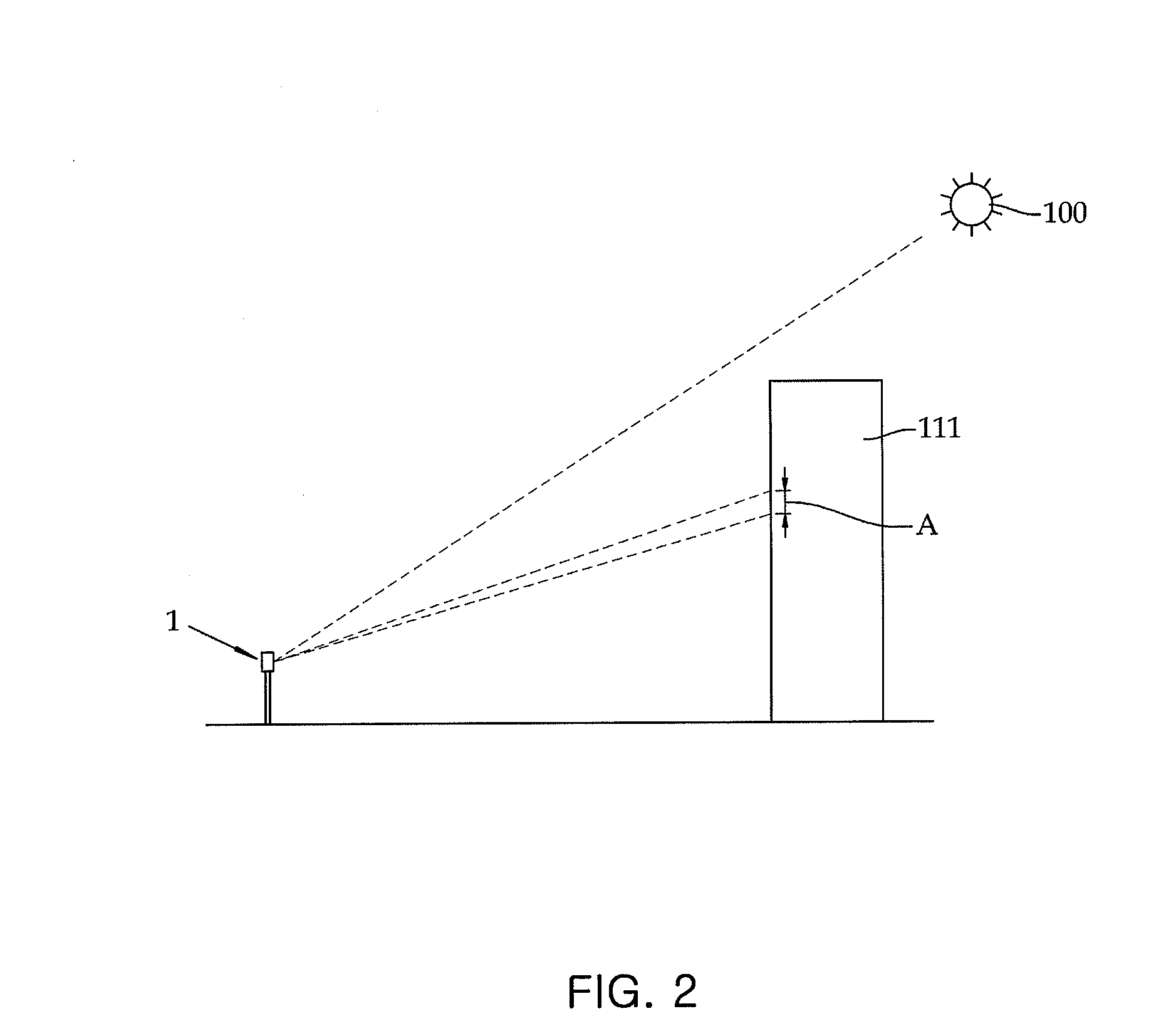
[0042]FIG. 2 illustrates an example where a natural lighting system (NLS) based on a sequential scanning mode according to an embodiment of the present invention is installed. It can be seen from FIG. 2 that the NLS is arranged so as to transmit light to a building 111, a shaded area of which is generated by the sun 100. Here, the natural lighting system 1 can be called a reverse natural lighting system. In detail, the reverse NLS employs a method of directly reflecting sunlight to transmit it to a desired scanning area.

[0043]FIG. 3 illustrates a detailed configuration of the reverse NLS of FIG. 2. According to an embodiment of the present invention, the NLS includes a reflector 10 that collects and reflects sunlight, and a sequential scanning drive 20 that continuously adjusts the reflector so as to allow the reflected light to be sequentially scanned wit...


PUM


Abstract

A natural lighting system tracks natural light or sunlight, effectively draws the light, distributes the light to necessary places, and sequentially scans the light on the scanning area. The natural lighting system collects the sunlight and then reflects the collected sunlight to a target scanning area based on a sequential scanning mode, and includes at least one reflector disposed according to an optimum control angle for collecting the sunlight, and a sequential scanning drive continuously adjusting the reflector so as to allow the sunlight transferred from the reflector to be sequentially scanned on the target scanning area.

Description

TECHNICAL FIELD[0001]The present invention relates to a natural lighting system, and more particularly, to a natural lighting system based on a sequential scanning mode, which tracks natural light or sunlight, effectively draws the light, distributes the light to necessary locations, and sequentially scans the light on a scanning area.BACKGROUND ART[0002]A natural lighting system for coping with sunshine blocking of low stories and their surroundings of high-rise buildings including apartment houses is disclosed in Korean Patent No. 10-0729721 (titled Natural Lighting System, and granted on Jun. 12, 2007). In the disclosed document, the natural lighting system includes a lighting unit and magnification reflecting means such that sunlight can be cast to a target scanning area on the basis of a position and / or a time. Among them, the lighting unit includes at least one reflector module for collecting the sunlight on a magnification reflecting unit.[0003]The natural lighting system of ...

Claims


Application Information

Patent Timeline
Patent Type & Authority Applications(United States)
IPC IPC(8): G02B7/182
CPCG02B26/0816F21V14/04F21S11/00E04F17/06E06B9/24
Inventor KIM, SEUNG-HAN
Owner KIM SEUNG HAN
Learn More