Methods and apparatus for generating and using visual error weights

Active Publication Date: 2010-09-30
ACCUSOFT PEGASUS
View PDF7 Cites 6 Cited by
  • Summary
  • Abstract
  • Description
  • Claims
  • Application Information

AI Technical Summary

Benefits of technology

[0011]In some embodiments, an integer order moment used to determine a visual error weight for a segment is generated by computing an average from two or more intermediate values corresponding to the segment which have been generated by raising wavelet transformed coefficients of the segment to an integer power. Alternatively the integer order moment may be generated by raising the absolute values of each of a plurality of coefficient values from the segment to an integer power and taking an average of the resulting intermediate values. All or a plurality of the coefficient values of a codeblock may be used in generating the integer order moment corresponding to the segment which is to be used in determining the weighting factor. Since the computation of the integer order moments of the codeblock is relatively simple, it does not add a great degree of complexity to the encoding process.
[0014]Through the use of the integer order moment and / or first order mean to determine a visual error weight, the invention provides a relatively low complexity method of generating visual error weights, on a per segment basis, which can take into consideration the activity and / or variance within a segment of a codeblock.
[0016]Through the use of the per segment visual error weight, greater allocation of coding bits can be applied to image areas which are generally more consistent, e.g., less busy, with more busy image segments being allocated fewer bits then would be allocated for the segment as compared to the case where an unweighted MSE was used.
[0031]In some embodiments, the weighted MSE is generated based on the visual weight generated from the integer order moments in accordance with the invention, a filter weight which is a function of the inverse impulse response of a wavelet filter used to generate the codeblock of wavelet transformed coefficients being encoded, and a contrast sensitivity weight. Through the use of the weight as a function of the integer order moments, greater coding emphasis than would be achieved without the use of the visual error weight is placed on low activity regions with lower emphasis on high activity regions. Use of the contrast scale factor can, and in some embodiments is, used to place greater emphasis on those wavelet bands the eye is most sensitive to in terms of bit allocation than would be provided without use of the weight. In this manner, there is a reduction in coding emphasis in regions where errors are hard to perceive and an increase in coding emphasis where coding errors are more likely to be perceived.

Problems solved by technology

While it is straightforward to define the size of an encoded image, the definition of “image quality” and thus of a quality metric is much harder.
The mean squared error between the original and the reconstructed image (MSE) is the most popular metric, but it is also known to be only a poor model for visual significance.
Due to the discrepancy between MSE used to control encoding and the perceived visual quality, reconstructed images sometimes show annoying artifacts.
Various attempts at improving upon the MSE approach have been limited in their success for a variety of reasons.
Some approaches have attempted to make modifications to the encoding process using fractional moments which can be very computationally complex to determine.
However, the computation of the fractional moment is a complex and time-consuming operation thereby significantly reducing the usefulness of such an approach.
More advanced approaches to improve coding have attempted to adjust quantizer bucket size dynamically on a per-coefficient basis but such approaches can be complex to implement, are incompatible with the JPEG2000 baseline, and are thus only available within part 2 of the JPEG2000 standard even if one is willing to accept the additional complexity associated with such a technique.

Method used


Image

  • Methods and apparatus for generating and using visual error weights
  • Methods and apparatus for generating and using visual error weights
  • Methods and apparatus for generating and using visual error weights

Examples


Embodiment Construction

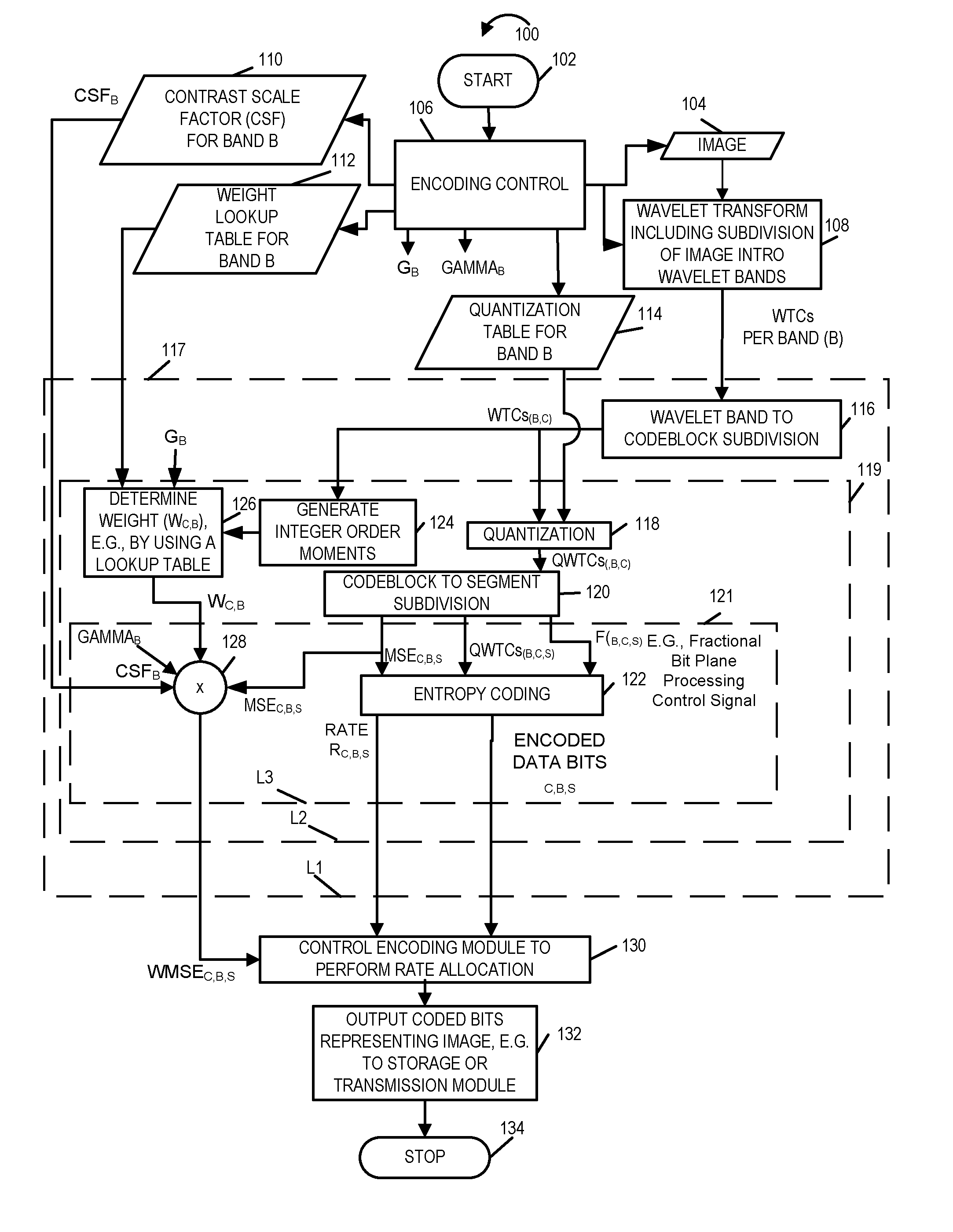
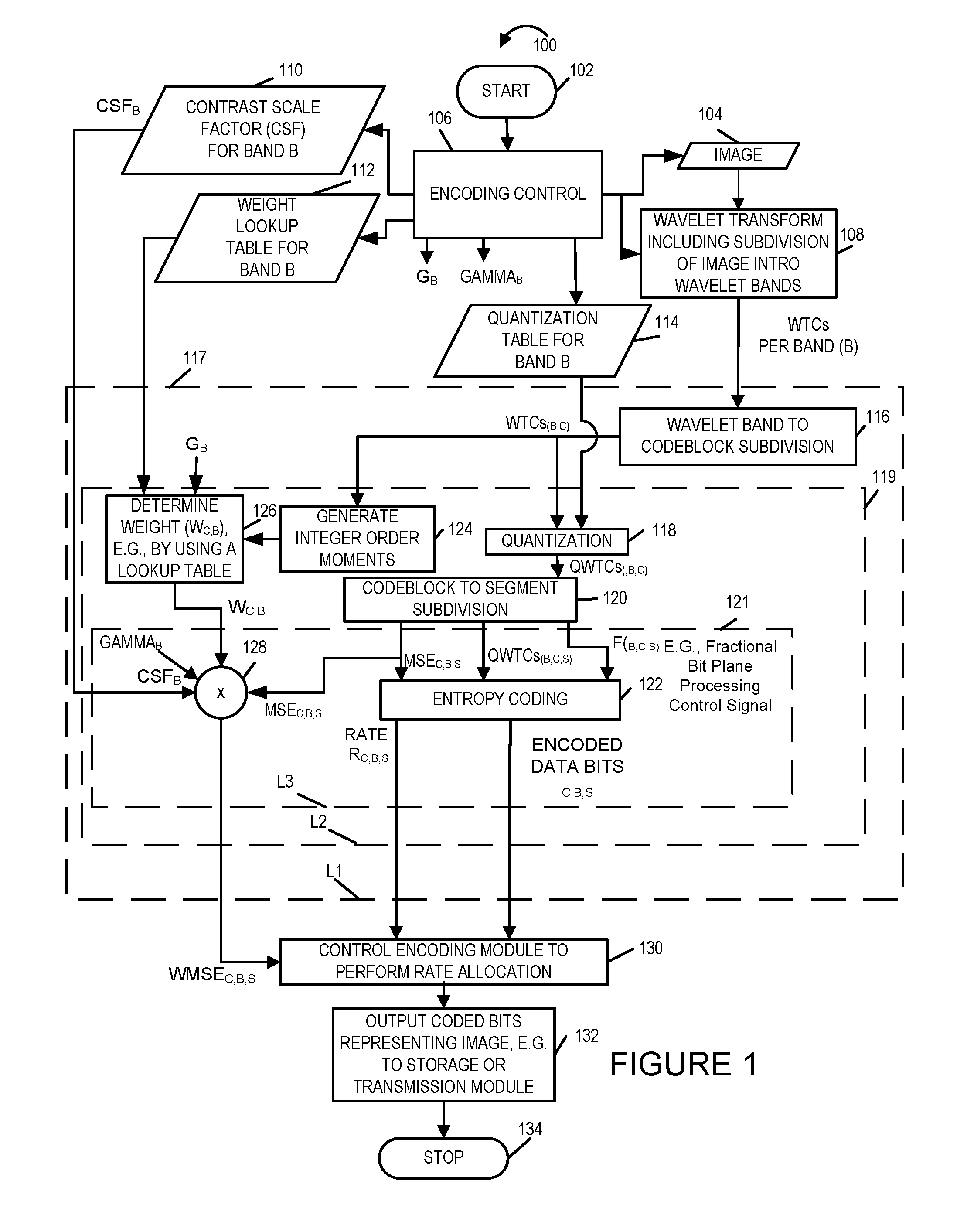
[0038]The present application is directed to low complexity visual masking methods and apparatus suitable for use in JPEG2000 image compression systems. In some embodiments, the visual masking techniques are implemented as part of a JPEG-2000 compliant encoder.

[0039]FIG. 1 illustrates an exemplary encoding method 100 implemented in accordance with the invention. The method is compatible with the JPEG-2000 standard. It is particularly well suited for use with gray scale images and can take advantage of variations within a codeblock with greater bit allocation emphasis being placed on less active image regions than image regions which are more active.

[0040]The method 100 begins in start step 102 wherein the system implementing the coding method, e.g., a computer system such as the one shown in FIG. 3, is initialized and one or more modules corresponding to the method 100 begin being executed by a processor used to implement the method. Operation proceeds from start step 102 to encodin...


PUM


Abstract

A low complexity visual masking method used as part of an image encoding process is described. The method is suitable for use in JPEG2000 image compression systems. Control weights used for rate allocation are generated based on integer order moments of wavelet transformed coefficients corresponding to a codeblock. The novel rate allocation weight generation method can, and in some embodiments is, combined with an apriori rate allocation algorithm, where allocation of bits to different portions of images is controlled as a function of one or more generated weights. The methods and apparatus of the present invention have the effect of increasing errors in busy areas of an image where they tend to be less noticeable and allocating a higher number of bits to less busy areas than some other systems, e.g., systems which attempt to minimize a mean squared error under a constraint of a user selected output rate.

Description

FIELD OF THE INVENTION[0001]The present invention relates to image encoding and, more particularly, to methods and apparatus for generating and using visual error weights, corresponding to portions of an image, in controlling image encoding, e.g., JPEG-2000 compliant image encoding.BACKGROUND[0002]The aim of rate allocation of an image compression codec is to find the coding parameters that optimize the image quality for a given target size, or to minimize the target size for a selected quality. While it is straightforward to define the size of an encoded image, the definition of “image quality” and thus of a quality metric is much harder. The mean squared error between the original and the reconstructed image (MSE) is the most popular metric, but it is also known to be only a poor model for visual significance.[0003]One known technique for encoding images is the JPEG 2000 image encoding format described in ISO / IEC document 15444-1. The JPEG2000 image compression algorithm uses the ...

Claims


Application Information

Patent Timeline
IPC IPC(8): G06K9/36
CPCH04N19/149H04N19/63H04N19/115H04N19/124H04N19/645H04N19/146H04N19/18H04N19/1883H04N19/14
Inventor RICHTER, THOMAS
Owner ACCUSOFT PEGASUS
Why Eureka
Try Eureka