Battery pack and power tool provided with the same

a battery pack and power tool technology, applied in the field of batteries, can solve the problems of damage or breakage of the electrode terminal, and achieve the effects of preventing excessive deformation, preventing the battery pack from being unsuitable, and reducing the stress on the circuit board produced in the connection time between the electrode terminal and the external electrode terminal

Active Publication Date: 2010-09-30
HITACHI KOKI CO LTD
View PDF8 Cites 22 Cited by
  • Summary
  • Abstract
  • Description
  • Claims
  • Application Information

AI Technical Summary

Benefits of technology

[0026]Hereby, it is possible to attach the battery pack within the range of the usable voltage to the electric device, and it is possible to prevent the battery pack over the usable voltage from being attached. Accordingly, it is possible to prevent the battery pack unsuitable for the electric device from being attached.
[0027]According to the eleventh aspect, since the shock applied from the outside is alleviated by the cushion member, the case inside can be protected. Further, the stress onto the circuit board produced in the connecting time between the electrode terminal and the external electrode terminal can be also alleviated.
[0028]According to the twelfth aspect, while perm

Problems solved by technology

In the battery pack, when the battery pack detached from the power tool is placed in a sideways falling-down state, in case that the shock is applied to the battery pack, if a portion that ha

Method used


Image

  • Battery pack and power tool provided with the same
  • Battery pack and power tool provided with the same
  • Battery pack and power tool provided with the same

Examples


Embodiment Construction

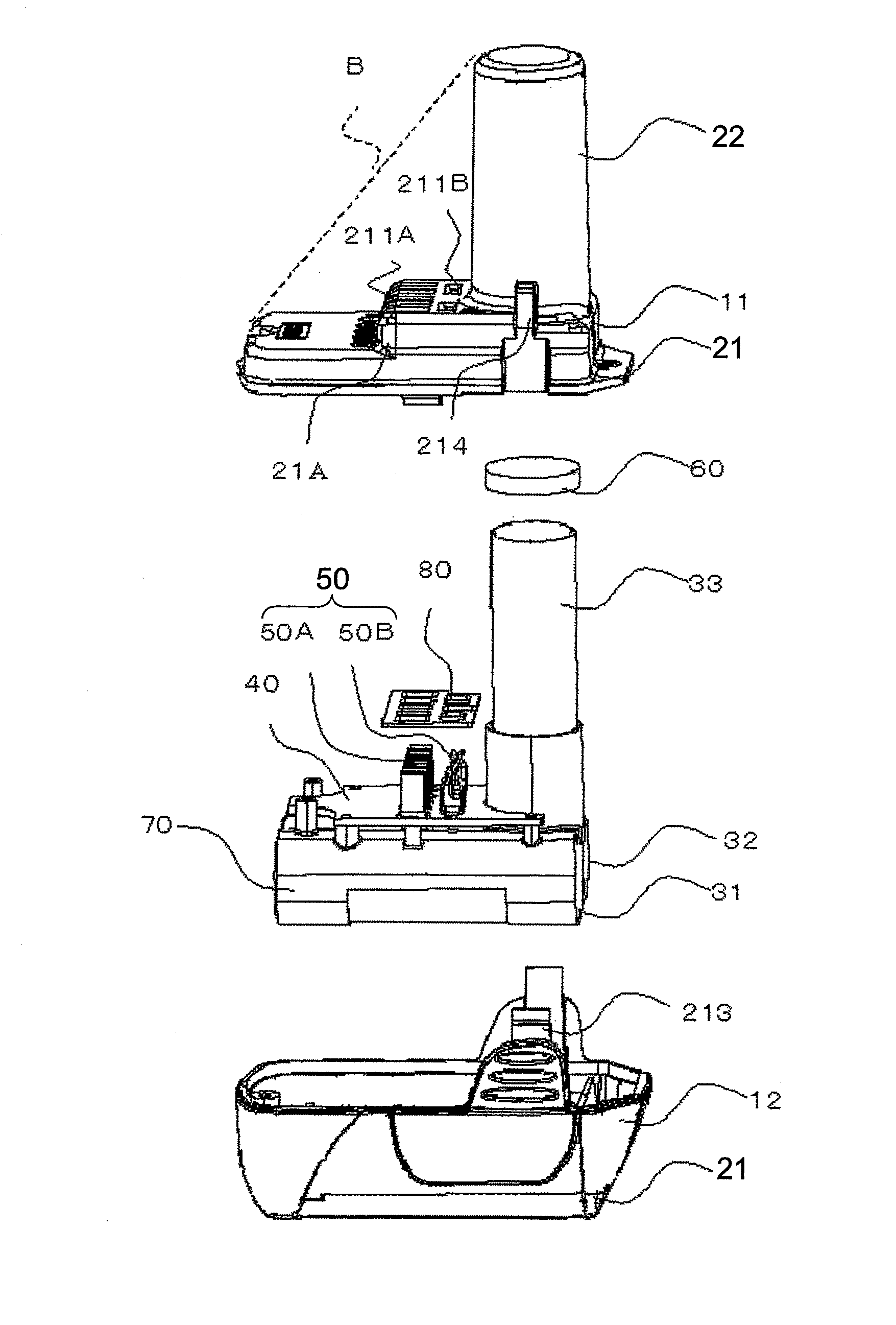
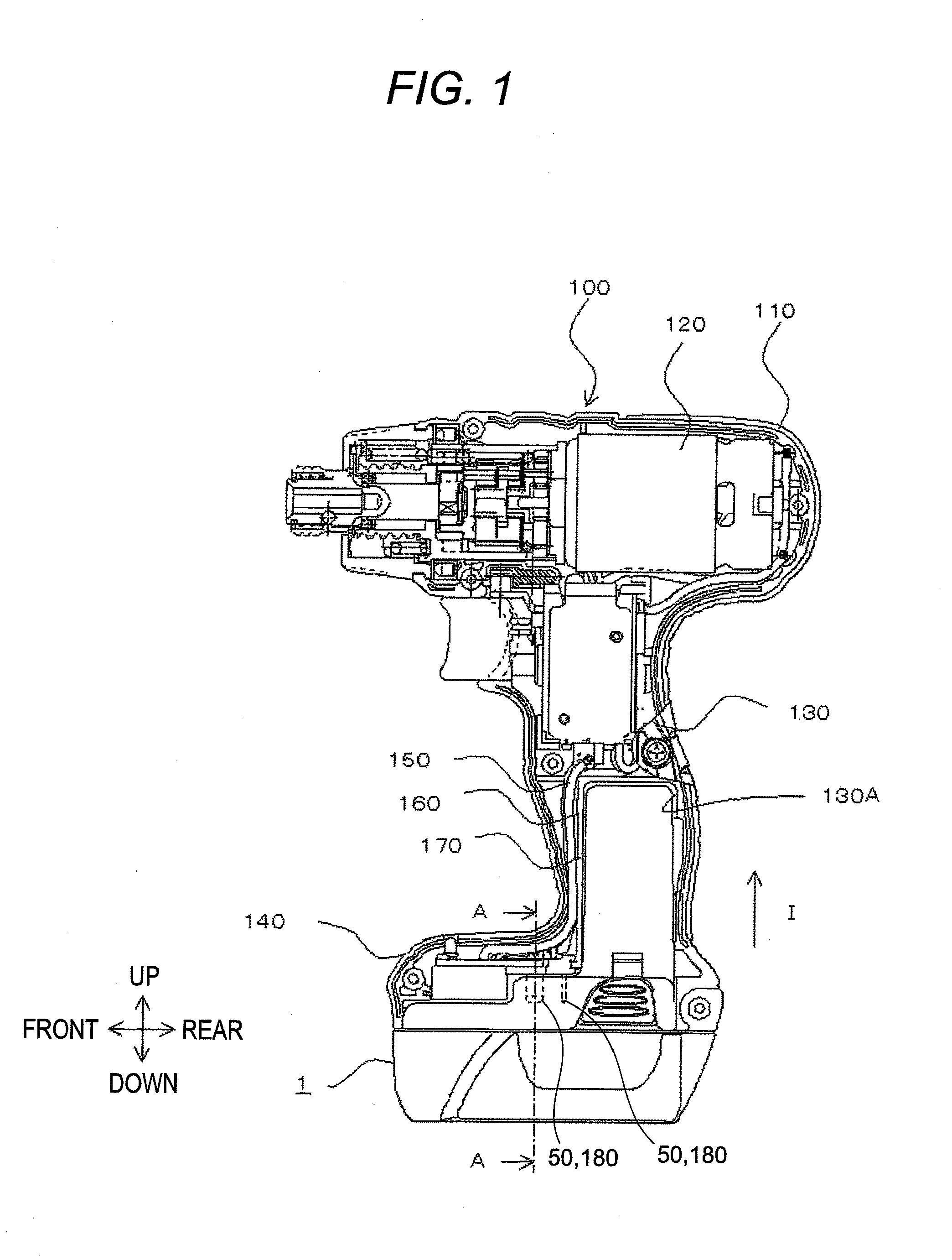
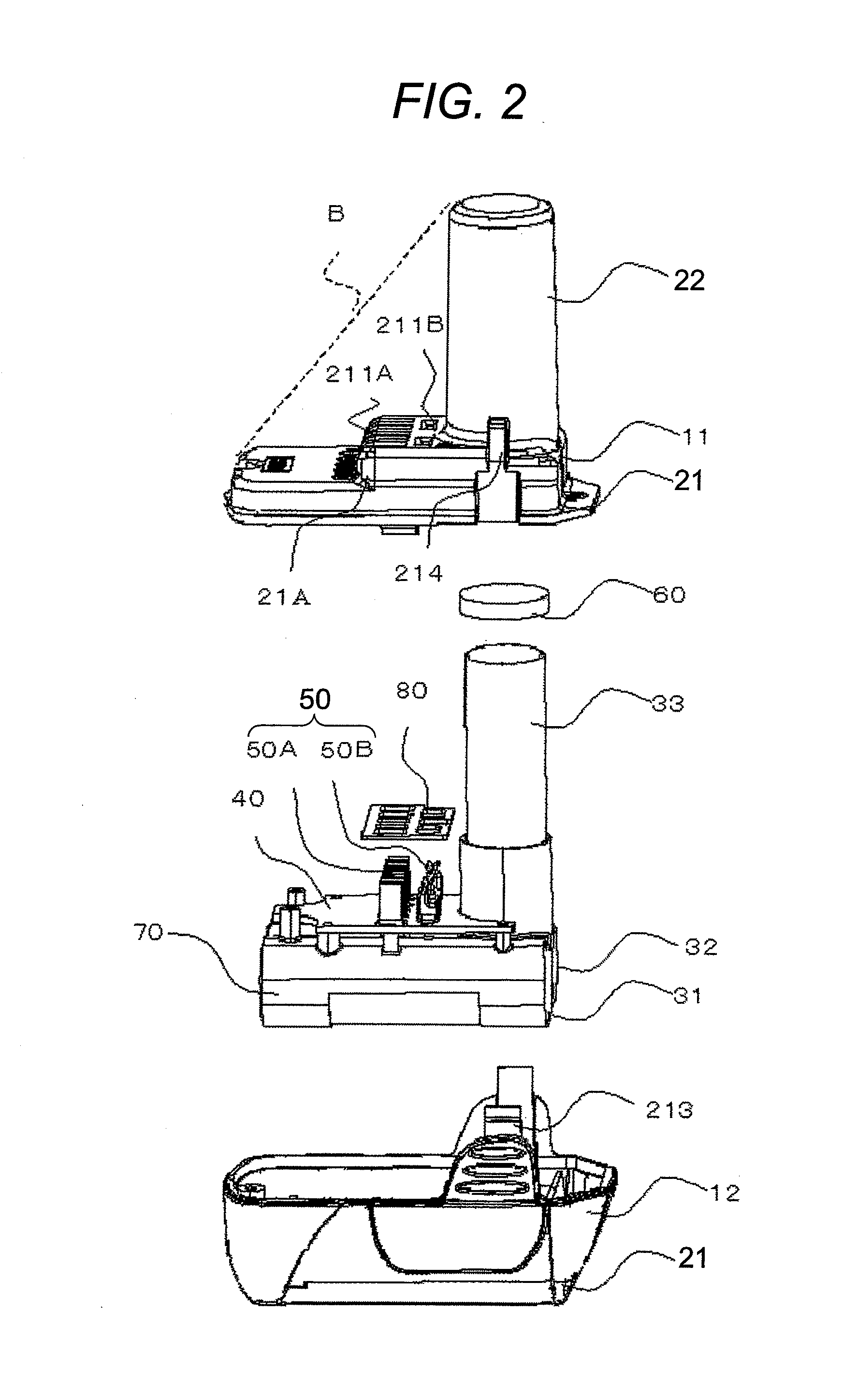
[0035]A driver drill according to an embodiment of the present invention will be described with reference to FIGS. 1 to 5. In FIG. 1, arrows indicating up-, down-, front- and rear-directions and an arrow 1 indicating an insertion direction of a battery pack 1 are shown. As shown in FIG. 1, a driver drill 100 is T-shaped in a side view. A main body part 110 of the driver drill 100 has horizontally-elongated shape, and a motor 120 functioning as a drive source is laterally accommodated in the main body part 110. A handle portion 130 for gripping downwardly extends from a central position of the main body part 110 at a lower side thereof. Further, at the lower end of the handle portion 130, a rectangular-shaped base 140 is formed, and the battery pack 1 is attached to the driver drill 100 from the downside of the base 140.

[0036]Inside the handle portion 130, there is formed an accommodation space 130A (accommodation part) for accommodating a case sub portion 22 of the battery pack 1 wh...


PUM


Abstract

According to an aspect of the present invention, there is provided a battery pack to be inserted and attached to a power tool, including: a case; a battery cell accommodated inside the case; and an electrode terminal connected to the battery cell and provided on the case so as to be connectable to a tool-side electrode terminal, wherein the case includes: a case main portion; and a case sub portion which is protruded from the case main portion to be inserted into the power tool, and wherein the electrode terminal is provided on an upper surface of the case main portion at a side of the case sub portion.

Description

TECHNICAL FIELD[0001]An aspect of the present invention relates to a battery pack in which an electrode terminal is surely protected, and a power tool provided with the battery pack.BACKGROUND ART[0002]For example, JP-2006-302759-A discloses a battery pack used in a power tool. In the battery pack, a battery case is L-shaped in a side view, and an electrode terminal to be connected to an electrode terminal of a power tool body is disposed at an upper end of the battery case.[0003]In the battery pack, when the battery pack detached from the power tool is placed in a sideways falling-down state, in case that the shock is applied to the battery pack, if a portion that has received its shock is in the vicinity of the electrode terminal, the shock is readily given onto the electrode terminal, with the result that the electrode terminal can be damaged or broken.DISCLOSURE OF INVENTION[0004]An object of the present invention is to provide a battery pack in which an electrode terminal is su...

Claims


Application Information

Patent Timeline
IPC IPC(8): H01M2/02B25F5/02H01M50/296
CPCH01M2/1055H01M2/1066H01M2220/30Y02E60/12H01M10/4257H01M2/30B25F5/02Y02E60/10H01M50/213H01M50/296
Inventor HANAWA, HIROYUKIFUJISAWA, HARUHISASAITOU, KEITA
Owner HITACHI KOKI CO LTD
Why Eureka
Try Eureka