
Plasma microwave resonant cavity

a microwave resonant cavity and microwave technology, applied in the field of resonance cavities, can solve the problems of increasing the attenuation affecting the processing quality of the optical fiber preform, and the stability of the product quality, so as to achieve the effect of reducing the difficulty of field installation, stable performance and quality of the produced optical fiber, and easy mounting and adjustmen

Active Publication Date: 2014-08-19
YANGTZE OPTICAL FIBRE & CABLE CO LTD
View PDF15 Cites 0 Cited by
  • Summary
  • Abstract
  • Description
  • Claims
  • Application Information

AI Technical Summary

Benefits of technology

The present invention provides a plasma microwave resonant cavity that can be easily mounted and detached with good installation quality and stable performance in use. The glass inner liner is securely positioned and tightly locked using a threaded mounting and locking structure, which prevents stress and cracking during use. The glass inner liner can be easily detached for maintenance and re-mounted, reducing maintenance costs and improving performance stability.

Problems solved by technology

The structure of the glass inner liner has the following problems: (1). the field installation is complex and of high operation difficulty, and since the quartz glass needs to be melted at a temperature above 2000° C., in this high-temperature environment, the metal at the end of the resonant cavity may easily diffuse to the quartz glass inner liner and further diffuse to a deposition tube in the PCVD deposition process, so that the attenuation of the optical fiber preform increases and affects the processing quality of the optical fiber preform; (2). the glass which is melted and then turned inside out has certain stress after cool down, so that glass cracking and breakage may easily occur in use, and in a more serious case, product rejection and even damages to the apparatus may be caused; (3). if the mounted glass ring gets loose in use, fastening is required; however, the effect of secondary fastening of glass is undesirable and can hardly reach the requirement, which may affect the processing performance of the apparatus as well as the stability of the product quality; and (4). since the quartz glass inner liner and the glass stop ring are adhered at a high temperature, destructive detachment needs to be performed on the quartz glass inner liner and the stop ring when the resonant cavity is maintained or checked, and in this case, a new glass inner liner needs to be replaced and the cracked glass fragment may easily fall into the resonant cavity to cause damages to the resonant cav
Therefore, a heretofore unaddressed need exists in the art to address the aforementioned deficiencies and inadequacies.

Method used


Image

  • Plasma microwave resonant cavity
  • Plasma microwave resonant cavity
  • Plasma microwave resonant cavity

Examples


Embodiment Construction

[0019]The present invention is more particularly described in the following examples that are intended as illustrative only since numerous modifications and variations therein will be apparent to those skilled in the art. Various embodiments of the invention are now described in detail in conjunction with the accompanying drawings. Referring to the drawings, like numbers indicate like components throughout the views.

[0020]In accordance with the purposes of this invention, as embodied and broadly described herein, this invention, in one aspect, relates to a rotary seal chuck deposed at a plasma microwave resonant cavity usable for a PCVD optical fiber preform rod lathe.

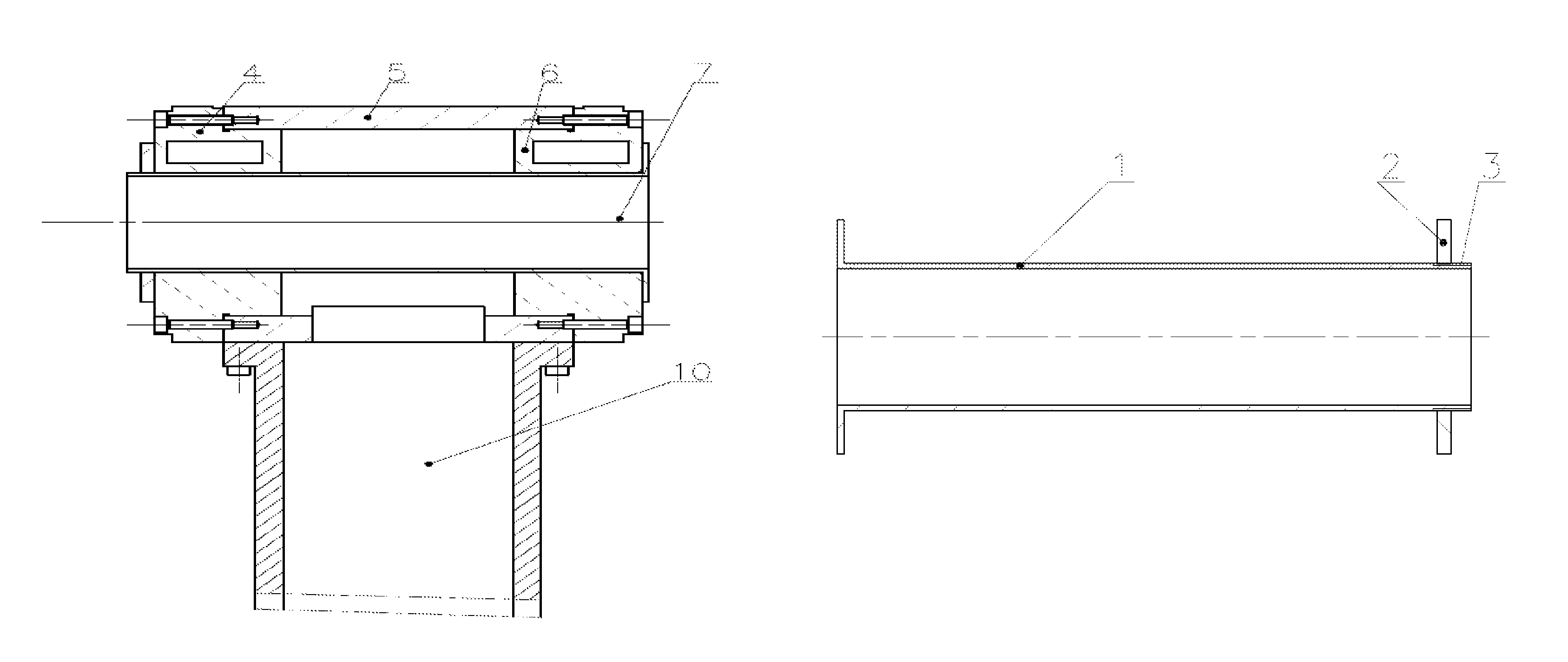
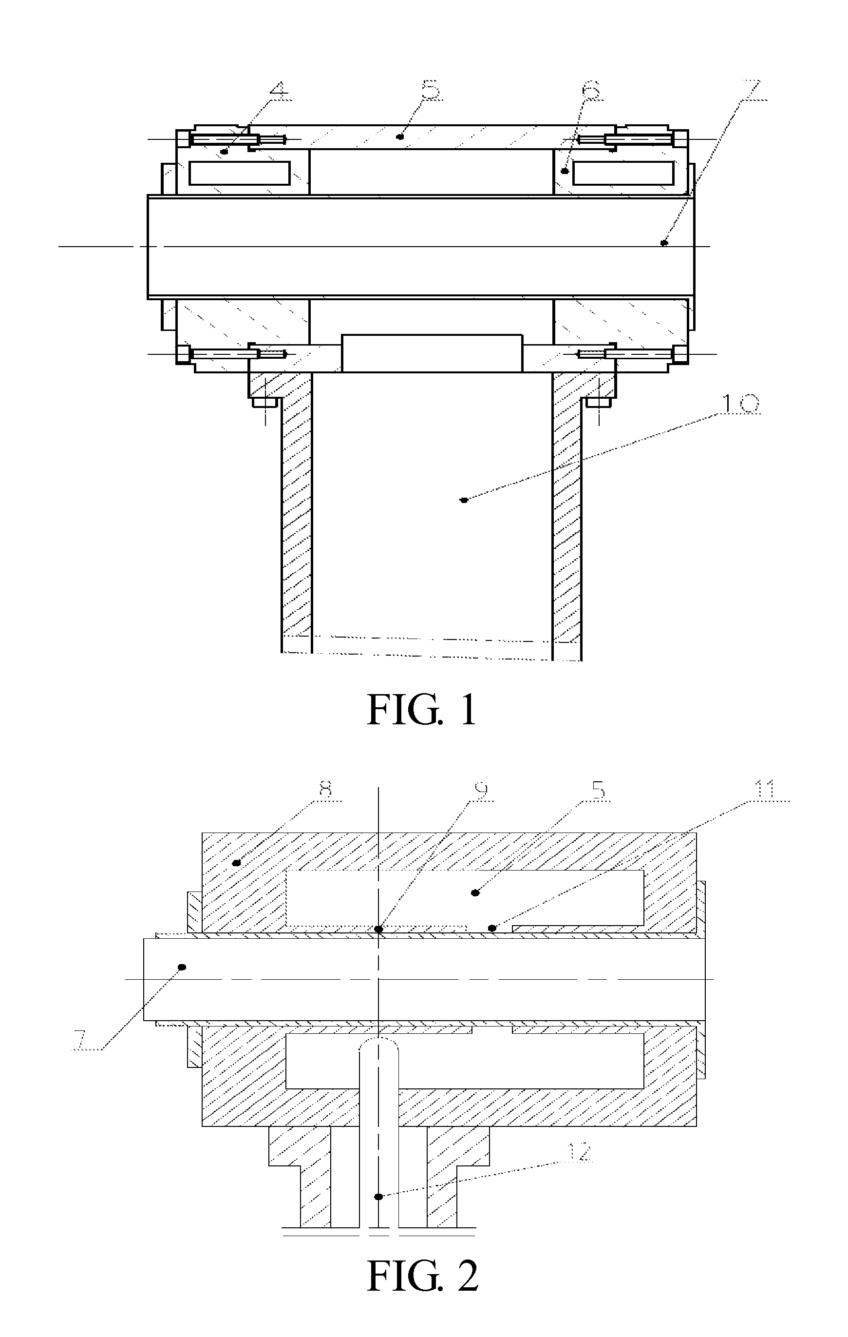
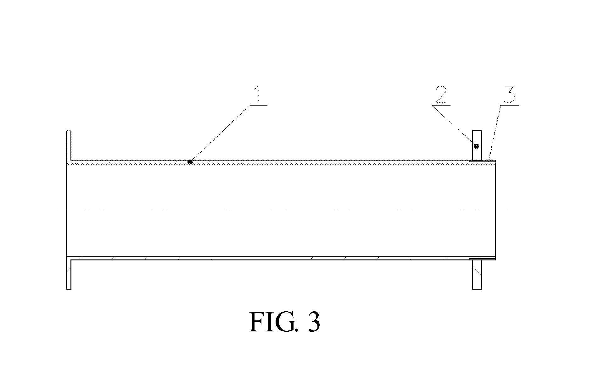
[0021]A first embodiment shown in FIGS. 1 and 3 provides a cylindrical resonant cavity, which includes a resonant cavity housing 5 and a waveguide device 10 connected to one side of the resonant cavity housing 5. A left and right end covers 4, 6 are disposed at two ends of the resonant cavity housing. The left and righ...


PUM

PropertyMeasurementUnit
axial lengthaaaaaaaaaa
diameteraaaaaaaaaa

Abstract

A plasma microwave resonant cavity used for a plasma chemical vapor deposition (PCVD) apparatus comprises a resonant cavity housing and a waveguide device connected with the cavity housing. Two ends of the cavity housing are provided with coaxial through-holes along the axial direction of the cavity. A glass inner liner is arranged through the through-holes at the two ends, and runs through a cavity body and the through holes at the two ends. The glass inner liner comprises a glass cylinder and glass stop rings arranged at the two ends of the glass cylinder. One or two ends of the glass cylinder are provided with external threads. The glass stop rings are connected with the ends of the glass cylinder by screw holes formed on the glass stop rings.

Description

FIELD OF THE INVENTION[0001]The present invention relates generally to a resonant cavity; and more particularly, to a plasma microwave resonant cavity usable for a PCVD optical fiber preform rod lathe, which is an improvement to an existing plasma microwave resonant cavity.BACKGROUND OF THE INVENTION[0002]Plasma chemical vapor deposition (PCVD) is a main process for optical fiber preform rod processing, and a plasma microwave resonant cavity is a core part of a PCVD processing apparatus. The plasma microwave resonant cavity mainly includes a resonant cavity housing and a waveguide device connected to the resonant cavity housing. Coaxial through-holes are opened on two ends of the resonant cavity housing along an axial direction of the resonant cavity, a glass inner liner is disposed via the through-holes at the two ends and penetrates the resonant cavity and the through-holes at the two ends, and glass stop rings are disposed at two ends of the glass inner liner and used for axial p...

Claims


Application Information

Patent Timeline
Patent Type & Authority Patents(United States)
IPC IPC(8): C23C16/00C03B37/018C23C16/511H01J37/32
CPCH01J37/32247C03B37/0183C23C16/511H01J37/32192H01J37/32229Y02P40/57
Inventor ZHANG, JINYANWANG, RUICHUNXIA, XIANHUI
Owner YANGTZE OPTICAL FIBRE & CABLE CO LTD
Learn More