Floor-cleaning equipment

a technology for cleaning equipment and floors, applied in the direction of vehicle cleaning, photosensitive materials, instruments, etc., can solve the problem of difficult cleaning operation, and achieve the effect of improving cleaning performan

Inactive Publication Date: 2010-10-07
CARL FREUDENBERG KG
View PDF8 Cites 35 Cited by
  • Summary
  • Abstract
  • Description
  • Claims
  • Application Information

AI Technical Summary

Benefits of technology

[0004]An aspect of the invention is to develop the cleaning device further in such a way that the cleaning performance is improved, in particular when cleaning carpeted floors.

Problems solved by technology

However, the cloth holder is foldable and is rigidly connected to the base body, in such a way that the cloth holder engages with the floor to be cleaned even when said floor is rather obstructive, as is the case when cleaning carpeted floors for example.
In this case, the cloth holder makes the cleaning operation more difficult because of the high friction.

Method used


Image

  • Floor-cleaning equipment
  • Floor-cleaning equipment
  • Floor-cleaning equipment

Examples


Embodiment Construction

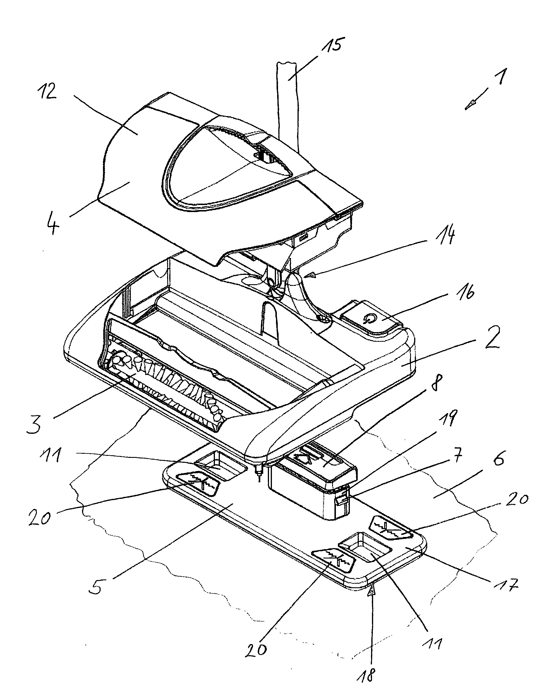
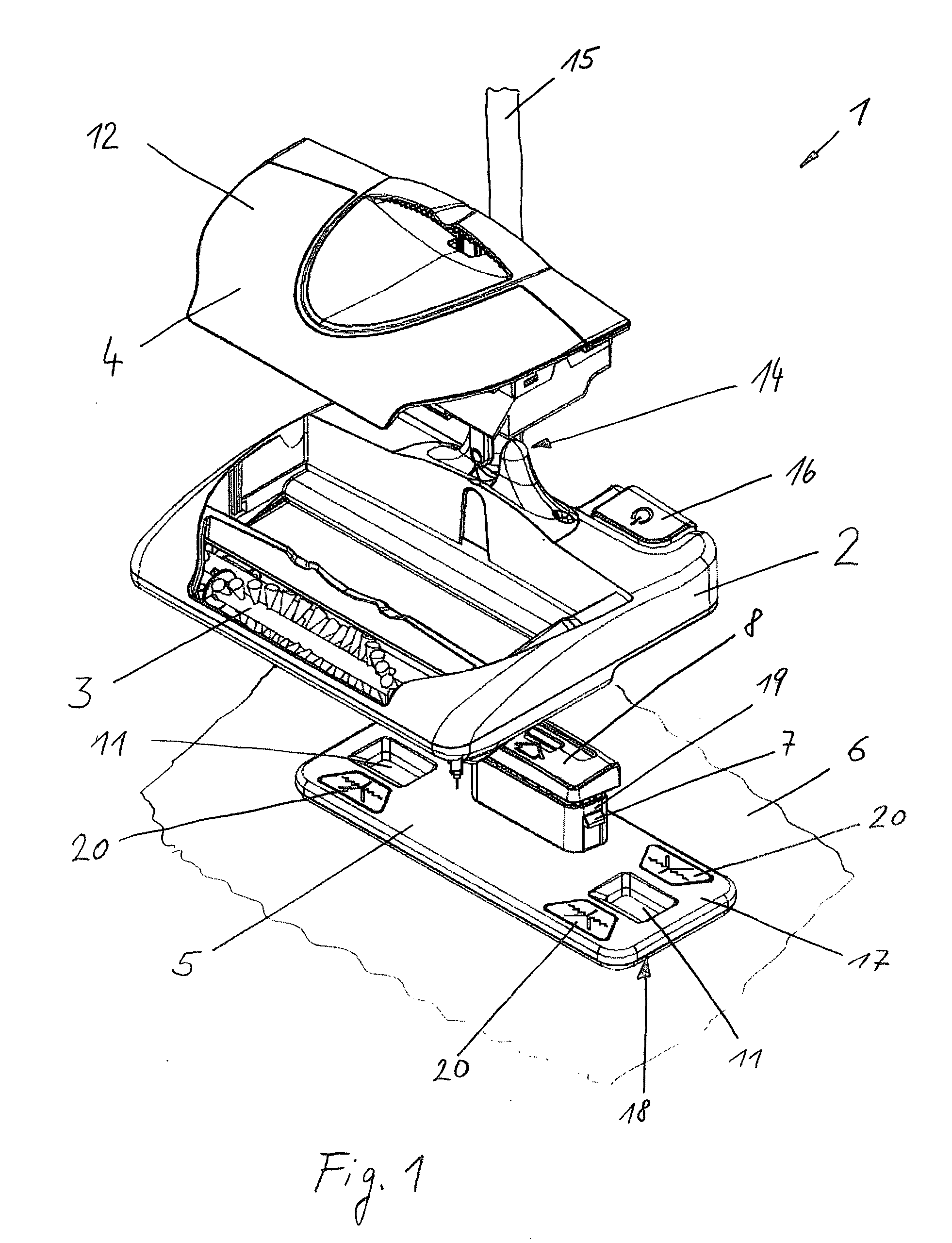
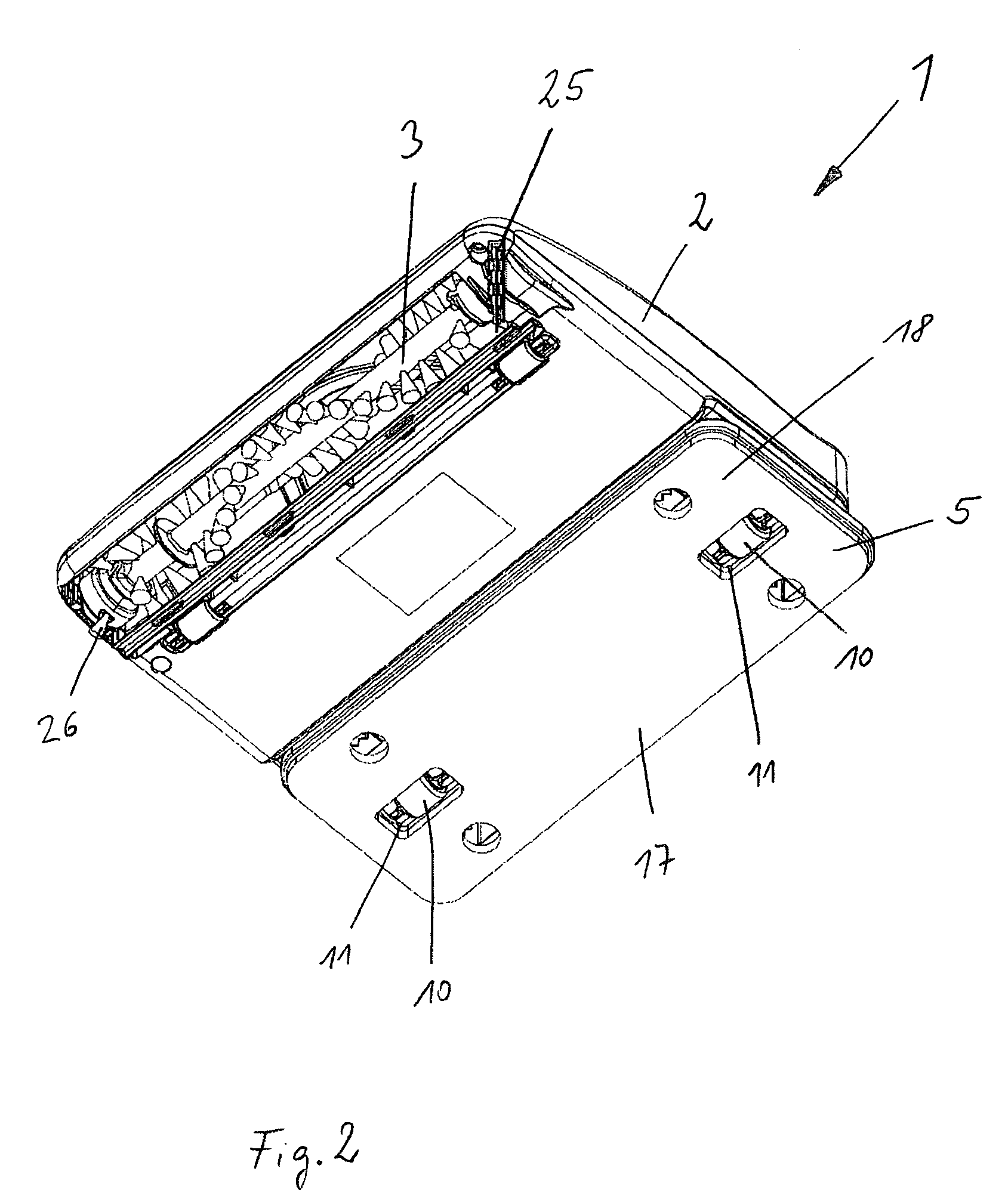
[0021]FIG. 1 shows a cleaning device 1, consisting of a base body 2 to which a handle 15 is connected via an articulation 14. The articulation 14 comprises a catch in such a way that the handle 15 can be locked folded up vertically by the base body 2 and cannot fall over. Furthermore, for mounting the handle 15 can be locked in a further position, specifically parallel to the base body 2, by means of the catch. In this way, the cleaning device 1 can be stored against or hung up on a wall in a space-saving manner. A rotatable brush roller 3 and a dirt container 4 are arranged in the base body 2. For this purpose, the base body 2 is opened in the direction of the floor to be cleaned, in such a way that the brush roller 3 engages with the floor to be cleaned. The brush roller 3 is driven via an electric motor, which is powered by rechargeable batteries, specifically lithium ion batteries. For switching the electric motor on and off, a switch 16 is located on the upper face of the base ...


PUM


Abstract

A cleaning device includes a base body, a rotatable brush roller disposed on the base body, a dirt container disposed on the base body, a cloth holder attached removably to the base body, and a cleaning cloth attachable to the cloth holder.

Description

CROSS REFERENCE TO PRIOR APPLICATIONS[0001]This application is a U.S. National Phase Application under 35 U.S.C. § 371 of International Application No. PCT / EP2008 / 006418, filed on Aug. 5, 2008 and claims benefit to German Application No. DE 10 2007 056 843.8, filed on Nov. 23, 2007. The International Application was published in German on May 28, 2009 as WO 2009 / 065450 under PCT Article 21 (2).[0002]The invention relates to a cleaning device, comprising a base body on which a rotatable brush roller and a dirt container are arranged and a cloth holder to which a cleaning cloth can be attached.BACKGROUND[0003]A cleaning device of this type is known from U.S. Pat. No. 7,013,528 B2. The previously known cleaning device consists of a base body to which a rotatable brush roller driven by an electric motor is attached, said roller transporting the dirt which is picked up into a dirt container arranged behind the brush roller. The brush roller picks up coarse dirt, which is picked up and re...

Claims


Application Information

Patent Timeline
Patent Type & Authority Applications(United States)
IPC IPC(8): A47L13/00
CPCA47L11/33A47L11/4013A47L13/256A47L11/4036A47L11/4041A47L11/4025
Inventor ARNOLD, PETER
Owner CARL FREUDENBERG KG
Why Eureka
Try Eureka