Magnetic sensor and magnetic sensor module

a magnetic sensor and module technology, applied in the field of magnetic sensors, can solve the problems of reducing the resistance of the intermediate permanent magnet layer, and achieve the effects of reducing the height of the magnetic sensor module, and efficient arrangemen

Active Publication Date: 2010-10-07
ALPS ALPINE CO LTD
View PDF4 Cites 30 Cited by
  • Summary
  • Abstract
  • Description
  • Claims
  • Application Information

AI Technical Summary

Benefits of technology

[0016]In the present invention, the magnetic sensor preferably further includes a fixed resistance element serially connected to the magnetoresistive effect element with an output extracting unit therebetween, wherein the fixed resistance element includes a plurality of connected-element bodies each formed by connecting a plurality of element units, whose electrical resistance does not change in response to an external magnetic field, to each other with an intermediate permanent magnet layer therebetween in the same manner as the magnetoresistive effect element, and the ends of the connected-element bodies are electrically connected to each other with an outer permanent magnet layer therebetween so as to form a meandering shape.
[0017]In particular, the element units constituting the fixed resistance element are preferably composed of the same stacking component as that of the element units constituting the magnetoresistive effect element. In this case, the temperature coefficients of resistance (TCR) of the magnetoresistive effect element and the fixed resistance element can be equalized. The same stacking component herein constitutes a structure for providing the same temperature coefficient of resistance. Even if the order of layers stacked is changed or a magnetization direction is changed, the same advantages can be produced.
[0018]In the present invention, pad portions electrically connected to a sensor portion including the magnetoresistive effect element and the fixed resistance element are preferably all formed on only one side relative to the sensor portion. In this case, the pad portions can be efficiently arranged in a limited space, which can downsize the magnetic sensor.
[0019]In the present invention, preferably, the element units constituting the magnetoresistive effect element each include a fixed magnetic layer whose magnetization direction is fixed and a free magnetic layer whose magnetization direction is changed in response to an external magnetic field, the free magnetic layer being stacked on a nonmagnetic layer stacked on the fixed magnetic layer, and a fixed magnetization direction of the fixed magnetic layer is the element-width direction, the element-width direction being a sensitivity axis direction.
[0020]A magnetic sensor module includes a plurality of the magnetic sensors described above, wherein magnetoresistive effect elements are arranged such that sensitivity axes of at least a pair of the magnetoresistive effect elements included in the plurality of the magnetic sensors are perpendicular to each other.
[0021]The magnetic sensor module may be formed as a package having a substantially plate-like shape, and a surface on which at least one of the magnetoresistive effect elements included in the plurality of the magnetic sensors is formed may be perpendicular to a plate surface of the package. In this case, the magnetic sensor module is preferably a geomagnetic sensor configured to detect geomagnetisms in directions of an X axis, a Y axis, and a Z axis (height direction), the X axis and the Y axis being perpendicular to each other in a plane, the plane being perpendicular to the Z axis. This can decrease the height of the magnetic sensor module.

Problems solved by technology

This can decrease the resistance of the intermediate permanent magnet layer.

Method used


Image

  • Magnetic sensor and magnetic sensor module
  • Magnetic sensor and magnetic sensor module
  • Magnetic sensor and magnetic sensor module

Examples


example

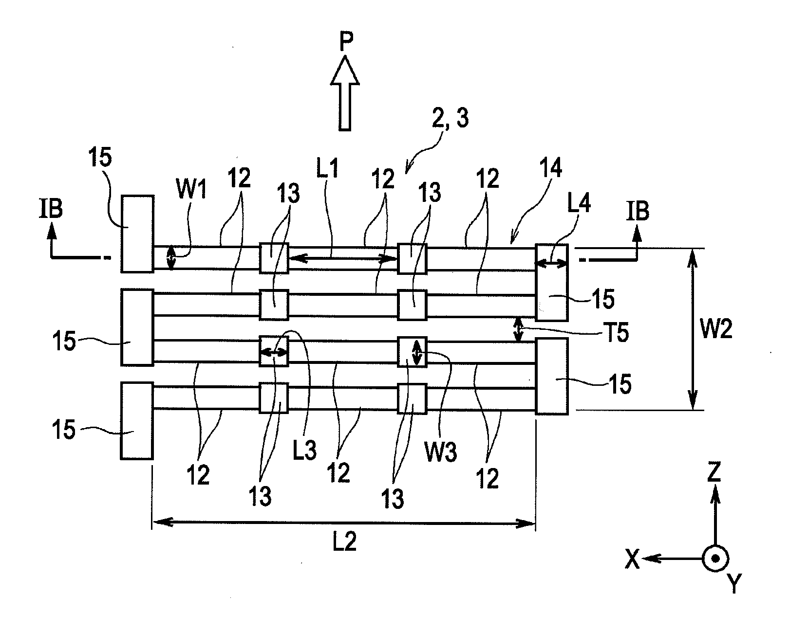
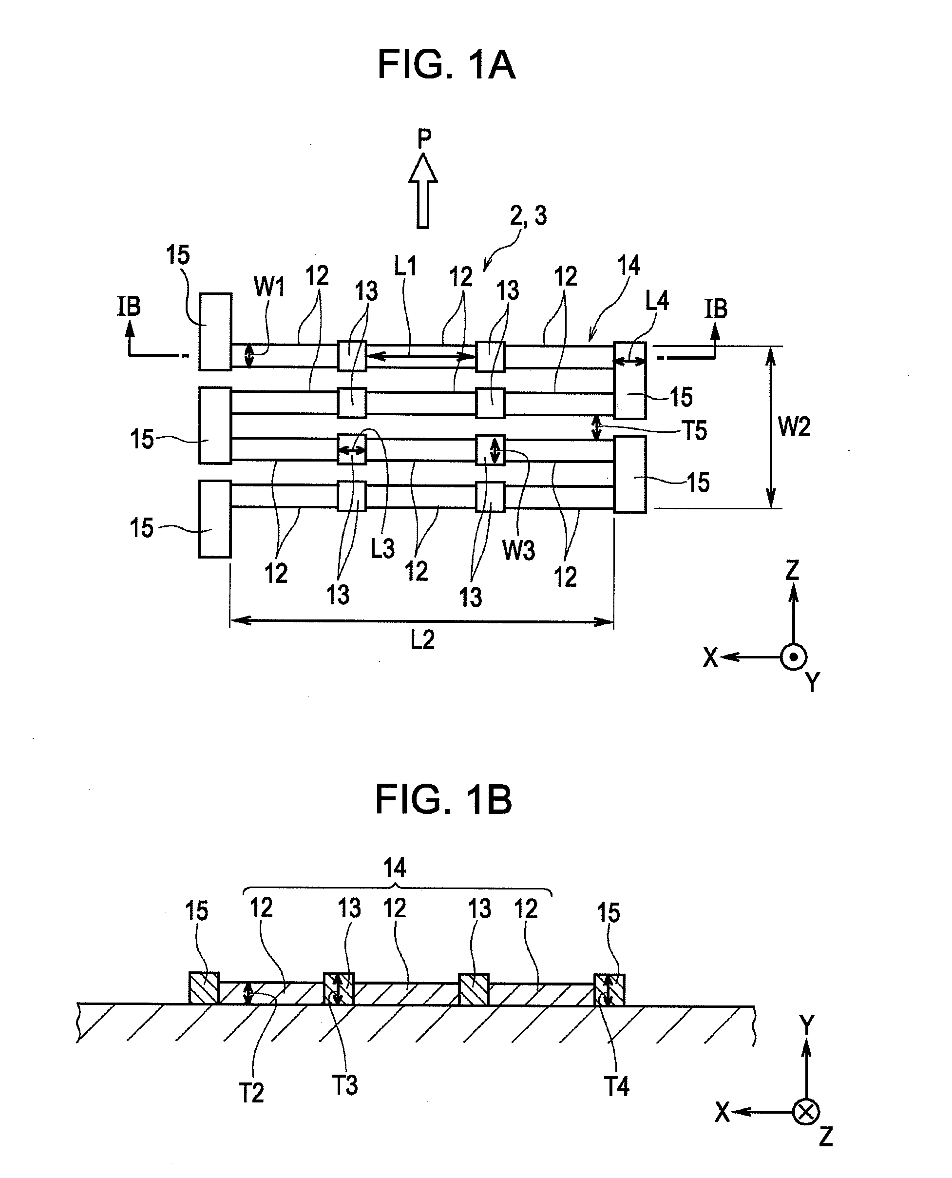
[0087]The magnetoresistive effect element shown in FIGS. 1A and 1B was formed. Forty-two element units 12 were arranged in connected-element bodies 14, and intermediate permanent magnet layers 13 (CoPt) each having a thickness of 200 Å were disposed between the element units 12. Each of the element units 12 was formed by stacking an antiferromagnetic layer (IrMn, thickness: 60 Å), a fixed magnetic layer (CoFe, thickness: 20 Å), a nonmagnetic layer (Cu, thickness: 21 Å), a free magnetic layer (NiFe, thickness: 30 Å), and a protective layer (Ta, thickness: 30 Å) in that order from the bottom. The element width W1 of the element units 12 was 4 μm and the element length L1 was 16 μm. The width W3 of the intermediate permanent magnet layers 13 was 9 μm and the length L3 was 5 μm. Six of the connected-element bodies 14 were arranged so as to be adjacent to one another in the element-width direction with a space of 2 μm. The ends of the connected-element bodies 14 were connected to each ot...


PUM


Abstract

A magnetic sensor including a magnetoresistive effect element has the following structure. Element units each having an element width W1 and an element length L1 perpendicular to the element width W1 and producing a magnetoresistive effect in which electrical resistance changes in response to an external magnetic field are arranged in an element-length direction with a space therebetween. An intermediate permanent magnet layer is disposed in the space, and the element units are connected to each other with the intermediate permanent magnet layer therebetween to form a connected-element body. A plurality of the connected-element bodies are arranged so as to be adjacent to one another in an element-width direction with a space therebetween, the ends of the connected-element bodies are connected to each other with an outer permanent magnet layer therebetween to form a magnetoresistive effect element having a meandering shape.

Description

CLAIM OF PRIORITY[0001]This application is a Continuation of International Application No. PCT / JP2008 / 072919 filed on Dec. 17, 2008, which claims benefit of the Japanese Patent Applications No. 2008-152705 filed on Jun. 11, 2008 and No. 2007-339501 filed on Dec. 28, 2007, both of which are hereby incorporated by reference.BACKGROUND OF THE INVENTION[0002]1. Field of the Invention[0003]The present invention relates to a magnetic sensor that uses a magnetoresistive effect element used as, for example, a geomagnetic sensor.[0004]2. Description of the Related Art[0005]A magnetic sensor that uses a magnetoresistive effect element can be used as, for example, a geomagnetic sensor configured to detect geomagnetism and mounted in a mobile apparatus such as a cellular phone. In the magnetoresistive effect element, an electrical resistance value changes in response to the magnetic field intensity in a sensitivity axis direction.[0006]As disclosed in Japanese Unexamined Patent Application Publ...

Claims


Application Information

Patent Timeline
Patent Type & Authority Applications(United States)
IPC IPC(8): G01R33/02
CPCB82Y25/00G01R33/0005H01L43/08G01R33/093G01R33/09H10N50/10
Inventor SASAKI, HIROMITSUANDO, HIDETO
Owner ALPS ALPINE CO LTD
Why Eureka
Try Eureka