Liquid crystal display device and control method thereof

a liquid crystal display and display panel technology, applied in the direction of instruments, computing, electric digital data processing, etc., can solve the problems of inability to appropriately correct the difficulty of providing a temperature sensor in and the discrepancy between. to achieve the effect of accurately detecting the amount of incident light into the crystal display panel, and appropriately correcting the optical response characteristics of the liquid crystal display panel

Inactive Publication Date: 2010-10-07
SHARP KK
View PDF6 Cites 8 Cited by
  • Summary
  • Abstract
  • Description
  • Claims
  • Application Information

AI Technical Summary

Benefits of technology

[0022]With this arrangement, it is possible to perform the emphasis conversion process according to a look-up table selected in accordance with the temperature of the liquid crystal panel calculated by the panel temperature calculation section. This makes it possible to appropriately correct the optical response characteristics of the liquid

Problems solved by technology

In the above-described conventional techniques, however, it is difficult to provide a temperature sensor in a liquid crystal display panel.
In consequence, when a temperature of the liquid crystal display panel rises due to incident external light into the liquid crystal display panel, a

Method used


Image

  • Liquid crystal display device and control method thereof
  • Liquid crystal display device and control method thereof
  • Liquid crystal display device and control method thereof

Examples


Embodiment Construction

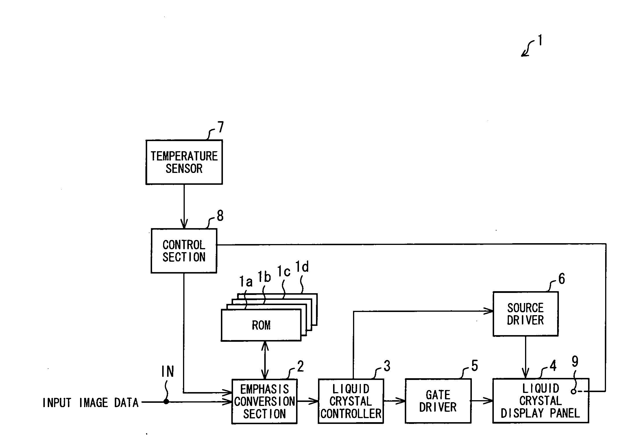
[0070]The following explains an embodiment of the present invention. FIG. 1 is a block diagram schematically illustrating a configuration of a liquid crystal display device 1 according to the present embodiment. This liquid crystal display device 1 is to be provided in a cellular phone, and includes a transmissive region and a reflective region. In the transmissive region, display is performed by transmitting light from a backlight through each pixel, while in the reflective region, display is performed by reflecting incident external light.

[0071]As illustrated in FIG. 1, the liquid crystal display device 1 includes OS table memories (ROMs, look-up tables) 1a to 1d, an emphasis conversion section 2, a liquid crystal controller 3, a liquid crystal display panel 4, a gate driver 5, a source driver 6, a temperature sensor 7, and a control section 8. The liquid crystal display panel 4 includes an optical sensor 9 that detects a light intensity of incident external light that enters the ...


PUM


Abstract

A liquid crystal display device (1) includes: an emphasis conversion section (2) performing an emphasis conversion process on image data of a current frame, based on an emphasis conversion parameter corresponding to a combination of image data of the current frame and image data of a frame immediately preceding the current frame; driving sections (3, 5, 6) causing a liquid crystal display panel (4) to display an image corresponding to the image data on which the emphasis conversion process has been performed by the emphasis conversion section (2); a temperature sensor (7) detecting an in-device temperature of the liquid crystal display device (1); an optical sensor (9) detecting a light intensity of incident external light into the liquid crystal display panel (4); and a control section (8) calculating a temperature of the liquid crystal display panel (4), based on the in-device temperature and the light intensity, and changing the emphasis conversion parameter to be used in the emphasis conversion process in accordance with the calculated temperature of the liquid crystal panel (4). Thus, even when the temperature of the liquid crystal display panel (4) is changed by the incident external light, optical response characteristics of the liquid crystal display panel (4) can be appropriately corrected.

Description

TECHNICAL FIELD[0001]The present invention relates to a liquid crystal display device. More specifically, the present invention relates to a technique for improving optical response characteristics of a liquid crystal display panel by performing an emphasis conversion process on input image data.BACKGROUND ART[0002]Recently, display devices are required to have reduced weight and thickness as personal computers and television receivers decrease in weight and thickness. In response to such requirements, flat-panel display devices such as liquid crystal displays (LCDs) are becoming more common in place of cathode-ray tube (CRT) displays.[0003]These days, LCDs are widely used not only as display devices for computers but also as display devices for television receivers. As such, there are growing needs for displaying moving images on LCDs. However, LCDs generally have a response speed that is lower than a response speed of display devices such as CRTs. On this account, in general, LCDs...

Claims


Application Information

Patent Timeline
IPC IPC(8): G06F3/038G09G3/36
CPCG09G3/3648G09G2300/0443G09G2300/0456G09G2320/0252G02F2001/13312G09G2340/16G09G2360/144G02F1/133555G09G2320/041G02F1/13312
Inventor FURUKAWA, TOMOOFUJIOKA, KAZUYOSHI
Owner SHARP KK
Why Eureka
Try Eureka