Light Fixture

a technology of light fixtures and light tubes, applied in the field of light fixtures, can solve the problems of not being very thermally or energy efficient, not necessarily compliant with the dark skies initiative, and losing around 8% optical efficiency, so as to maximize the amount of direct light, minimize the thermal path, and maximize the effect of direct ligh

Active Publication Date: 2010-10-07
ABL IP HLDG
View PDF37 Cites 49 Cited by
  • Summary
  • Abstract
  • Description
  • Claims
  • Application Information

AI Technical Summary

Benefits of technology

[0012]Certain embodiments of the present invention provide a light fixture (including but not limited to an outdoor light fixture) that maximizes the amount of direct lighting into an intended area by using light engines with light sources that emit light directly towards the intended area. Also, the light fixture may be structurally configured to avoid obstruction of the emitted light but rather to ensure that the most light possible reaches the intended area. The light fixture may include a carriage with a first (top) end and a second (bottom) end opposite the first end. A hood may be mounted to the first end of the carriage. At least one light engine may be mounted to the hood. The light engine includes a plurality of light sources that emit light downwardly directly onto an intended area. In some embodiments, the light sources are light-emitting diodes. It may be desirable from a heat transfer and thermal efficiency perspective to mount the light engine(s) onto a mounting plate, which is subsequently mounted to the hood such that the light engines are in close proximity to the hood surface thus minimizing the thermal path for heat from the light engines to travel to the hood surface where it will be radiated and conducted off. Regardless, the light sources are preferably positioned on the light engines and the light engines preferably positioned on the hood so that light emitted from the light sources has an unobstructed path to the intended area. It is preferable, but not required, that the second end of the carriage be shaped and sized so that it does not interfere with emission of the light to the intended area. The light fixture thus provides light in a thermally efficient manner, maximizes the amount of direct light, and limits the amount of light pollution.

Problems solved by technology

This post top fixture 10 uses a mixture of indirect and direct lighting, and is not necessarily compliant with Dark Skies initiatives.
Nor is it very thermally or energy efficient.
When light passes through the panes 26, it can result in a loss of optical efficiency of around 8%.
If the panes 26 are dirty then optical efficiency and upward refraction and reflection are even more problematic.
Additionally, the panes 26 if constructed of glass or brittle plastic are subject to vandalism by people breaking the panes 26.
The panes 26 thus result in inefficiency and might create dangerous conditions.
Additionally, some of the light in traditional post top fixtures 10 is emitted upwardly, which wastes energy and violates Dark Skies initiatives.
But the cost of completely replacing existing post top fixtures 10 might be prohibitive, and results in landfill waste.

Method used


Image

  • Light Fixture
  • Light Fixture
  • Light Fixture

Examples


Embodiment Construction

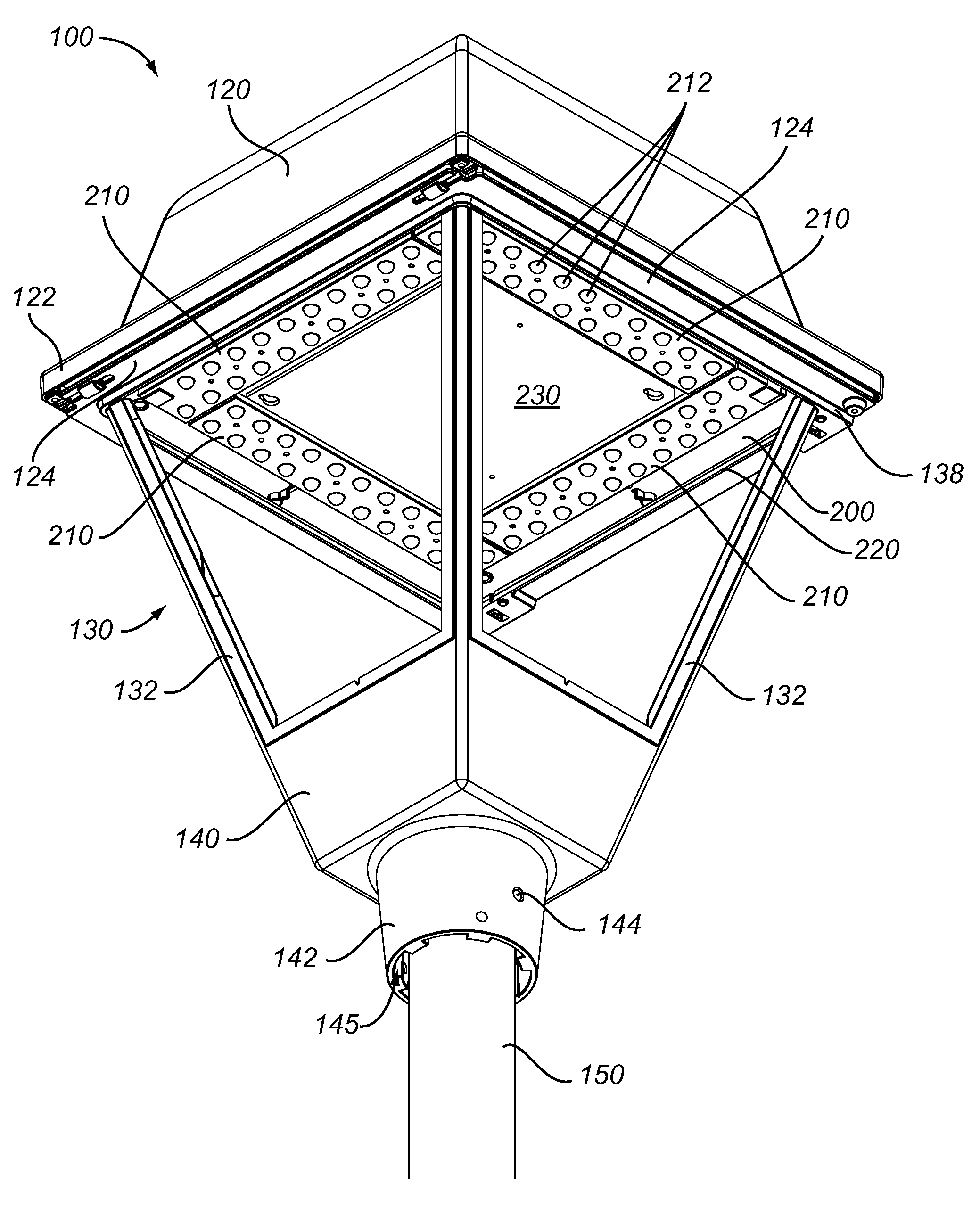
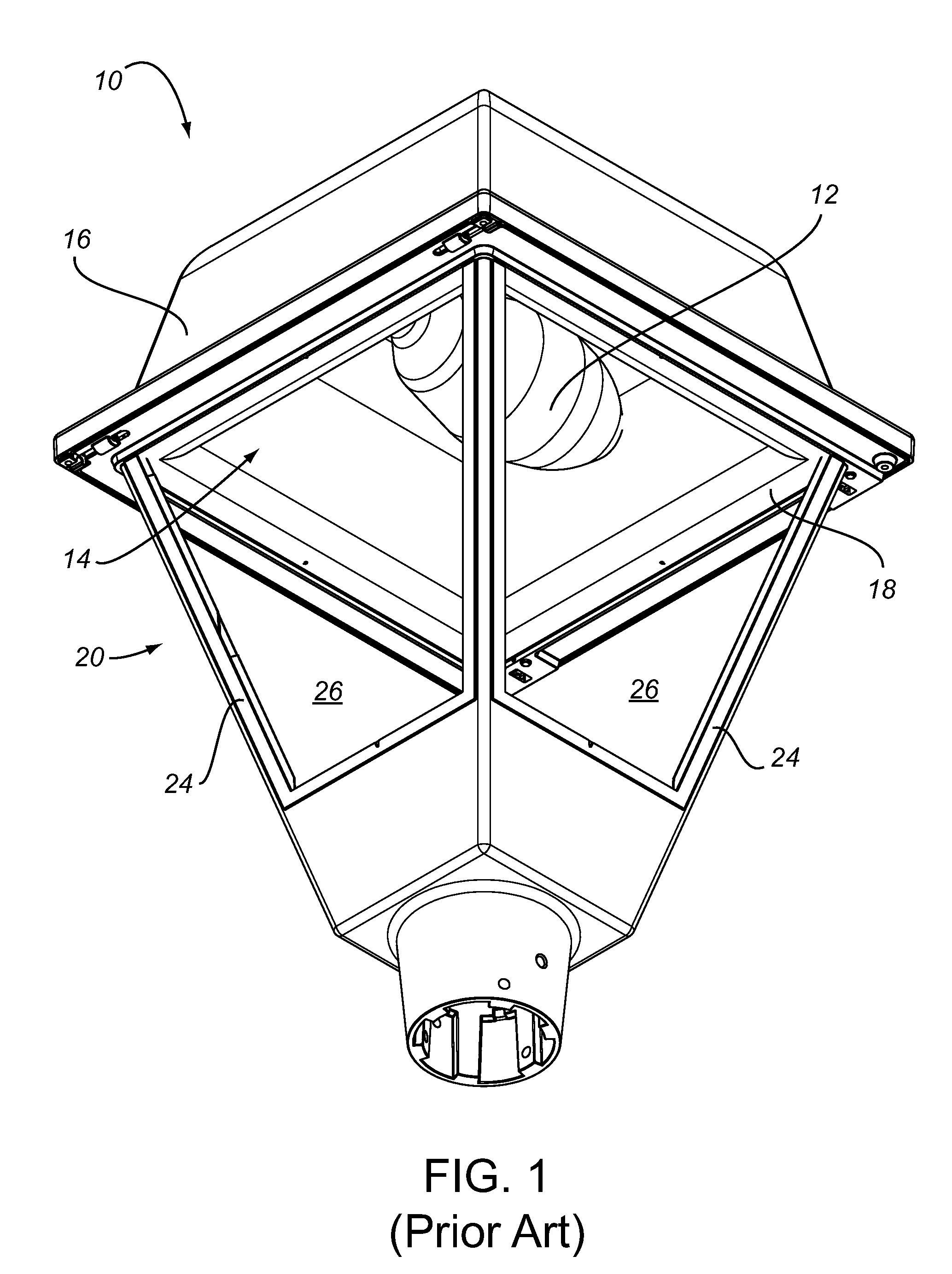
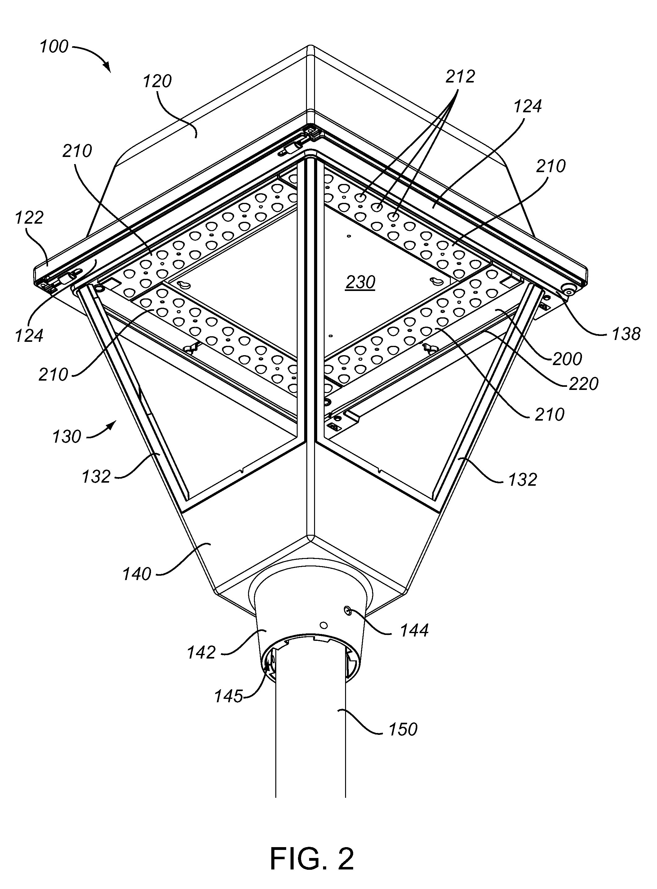
[0020]One embodiment of the light fixture 100 is shown in FIG. 2. Embodiments of the light fixture 100 may either be modified versions of existing post top fixtures 10 (as shown in FIG. 1), or they may be newly constructed light fixtures 100. One of skill in the art would understand how to modify an existing post top fixture 10 to create the light fixture 100 described herein.

[0021]One embodiment of a light fixture 100 may include a carriage 130 that has a first (top) end 138 and a second (bottom) end 140. Side arms 132 extend between the first end 138 and the second end 140, and the side arms 132 are connected by edges 124. While panes may be used, in certain embodiments there are no panes between the side arms 132 so that the space between the side arms 132 is open. Such embodiments might be useful to increase the optical efficiency of the light fixture 100 (because panes may result in a loss of optical efficiency of around 8%) and to minimize any upward refraction or reflection c...


PUM


Abstract

Light fixtures having a plurality of light-emitting diodes that maximize the amount of direct light into an intended area. The light fixture may include a carriage with a first (top) end and a second (bottom) end. A hood may be mounted to the first end of the carriage. At least one light engine comprising a plurality of light sources is mounted to the hood. The light sources emit light downwardly directly onto an intended area. In certain embodiments the second end of the carriage is shaped and sized so that it does not interfere with emission of the light to the intended area. The light fixture thus provides light in a thermally efficient manner, maximizes the amount of direct light, and limits the amount of light pollution.

Description

CROSS-REFERENCE TO RELATED APPLICATIONS[0001]This application claims to the benefit of Application Ser. No. 61 / 211,725, filed on Apr. 2, 2009 and entitled “Light Fixture,” the entire contents of which are incorporated by reference.FIELD OF THE INVENTION[0002]Embodiments of the present invention relate to light fixtures using direct light.BACKGROUND OF THE INVENTION[0003]Energy efficiency and environmental impact have become areas of great concern for society. Thus, many cities have adopted “Dark Skies” initiatives that aim to reduce light pollution by encouraging reduced amounts of light in the nocturnal environment. These initiatives encourage using less light in general, using controls (such as on-off capabilities and time-of-night sensors), and using reflectors and shields to reduce nocturnal light. Such measures may result in energy savings resulting in economic benefits, better nighttime ambience and quality of life, conservation of nocturnal wildlife and ecosystems, and increa...

Claims


Application Information

Patent Timeline
Patent Type & Authority Applications(United States)
IPC IPC(8): F21V1/00F21S4/00
CPCF21K9/00F21S8/088F21V15/01F21Y2101/02F21V31/04F21W2131/10F21V21/116F21Y2115/10
Inventor MCCANLESS, FORREST S.
Owner ABL IP HLDG
Why Eureka
Try Eureka