Gas turbine inner flowpath coverpiece

a technology of gas turbines and inner flow paths, which is applied in the direction of machines/engines, stators, liquid fuel engines, etc., can solve the problems of reducing the efficiency of gas turbines, requiring excess maintenance, and current solutions affecting engine performance,

Active Publication Date: 2010-10-07
GENERAL ELECTRIC CO
View PDF4 Cites 7 Cited by
  • Summary
  • Abstract
  • Description
  • Claims
  • Application Information

AI Technical Summary

Problems solved by technology

Gaps between stationary and rotating parts could cause this gas to reach the wheel materials and cause them to require excess maintenance.
Cavity purging implements pressurized air that leaks into the hot gas path in the gas turbine, thereby reducing the efficiency of the gas turbine

Method used


Image

  • Gas turbine inner flowpath coverpiece
  • Gas turbine inner flowpath coverpiece
  • Gas turbine inner flowpath coverpiece

Examples


Embodiment Construction

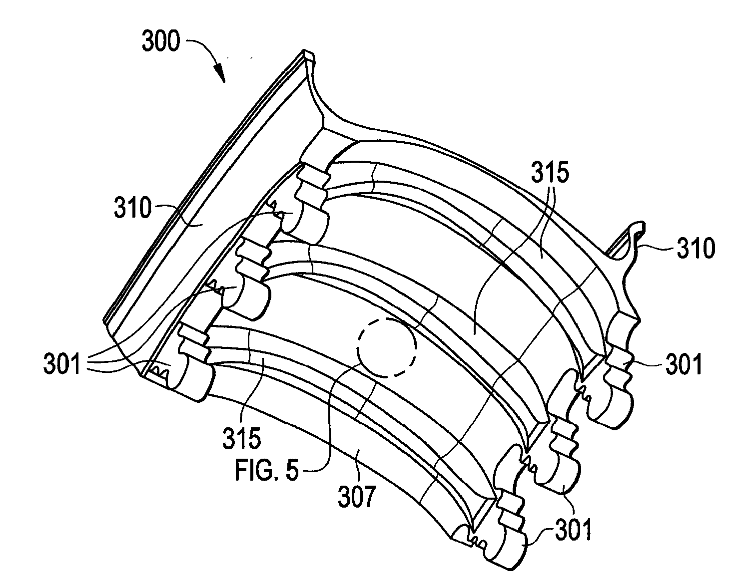
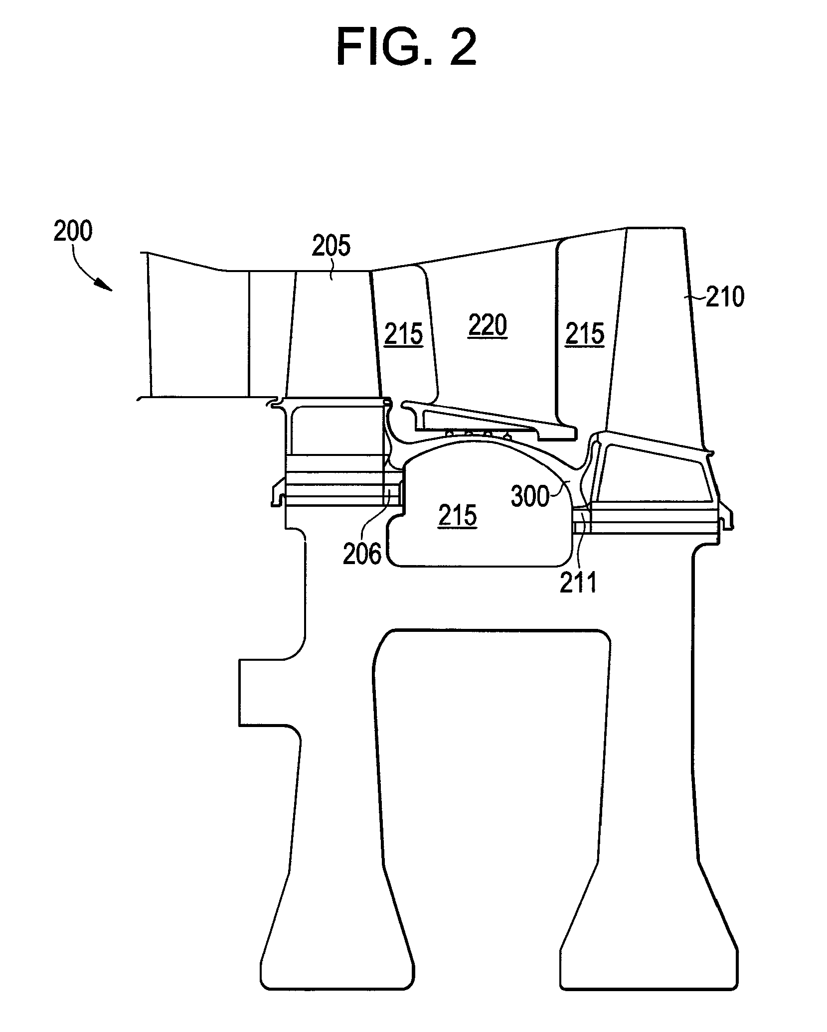
[0015]FIG. 2 illustrates a gas turbine configuration 200 including an exemplary gas turbine inner flow path cover piece 300. In exemplary embodiments, the configuration 200 includes adjacent turbine wheels 205, 210 having a cavity 215 disposed between the turbine wheels 205, 210. The configuration 200 further includes the gas turbine inner flow path cover piece 300 disposed between the turbine wheels 205, 210. It is appreciated that in exemplary embodiments, the conventional diaphragm (see the diaphragm 121 in FIG. 1) is removed. The configuration 200 further includes a hot section turbine nozzle 220 that provides the cool air for cavity purging as described herein. With the disposition of the gas turbine inner flow path cover piece 300 between the adjacent turbine wheels 205, 210, the aforementioned cavity purging can be greatly reduced because there is a reduced upper cavity 225 directly exposed to the hot gas path temperatures. A lower cavity 215 is not exposed to the hot air flo...


PUM


Abstract

A gas turbine inner flow path cover piece for a gas turbine a first turbine wheel and a second turbine wheel is provided is provided. The gas turbine inner flow path cover piece can include a main body having an first surface and a second surface, side pieces disposed on the first surface of the main body and mating pairs disposed on the second surface of the main body.

Description

BACKGROUND OF THE INVENTION[0001]The subject matter disclosed herein relates to gas turbines, and more particularly to a gas turbine inner flow path cover piece.[0002]FIG. 1 illustrates a prior art gas turbine configuration 100. In typical hot gas section designs, such as the configuration 100, turbine wheels 105110, including airfoil slots 101, are not designed to withstand the high temperatures of the combustion gas within the turbine. Gaps between stationary and rotating parts could cause this gas to reach the wheel materials and cause them to require excess maintenance. As such, cooler air is introduced into a cavity 115 in between wheels 105, 110 that pressurizes the cavity 115, preventing hot air from leaking into the cavity 115. A diaphragm 121 is typically included to fill the cavity 115. The process of introducing the cooler air is referred to as cavity purging. Cavity purging implements pressurized air that leaks into the hot gas path in the gas turbine, thereby reducing t...

Claims


Application Information

Patent Timeline
IPC IPC(8): F01D11/00
CPCF05D2260/36F01D11/001
Inventor GARCIA-CRESPO, ANDRES JOSEBOYER, BRADLEY TAYLORHARRIS, JR., JOHN WESLEYPOTTER, BRIAN DENVERWILSON, IAN DAVID
Owner GENERAL ELECTRIC CO
Why Eureka
Try Eureka