Connector

a technology of connecting rods and shielding devices, applied in the direction of coupling device connections, coupling protective earth/shielding arrangements, electric discharge lamps, etc., can solve the problems of difficult liable to occur crosstalk, and achieve the effect of suppressing crosstalk and easy to carry out impedance matching

Inactive Publication Date: 2010-10-07
JAPAN AVIATION ELECTRONICS IND LTD
View PDF4 Cites 19 Cited by
  • Summary
  • Abstract
  • Description
  • Claims
  • Application Information

AI Technical Summary

Benefits of technology

[0014]The present invention has been made in view of these circumstances, and an object thereof is to provide a connector which is capable of

Problems solved by technology

As described above, the distance between the plus and minus signal lines SL′ and SL′ on the printed circuit board 21′ is partially increased, whereby a range in which the plus and minus signal lines SL′ and SL′ are not parallel

Method used


Image

  • Connector
  • Connector
  • Connector

Examples


first embodiment

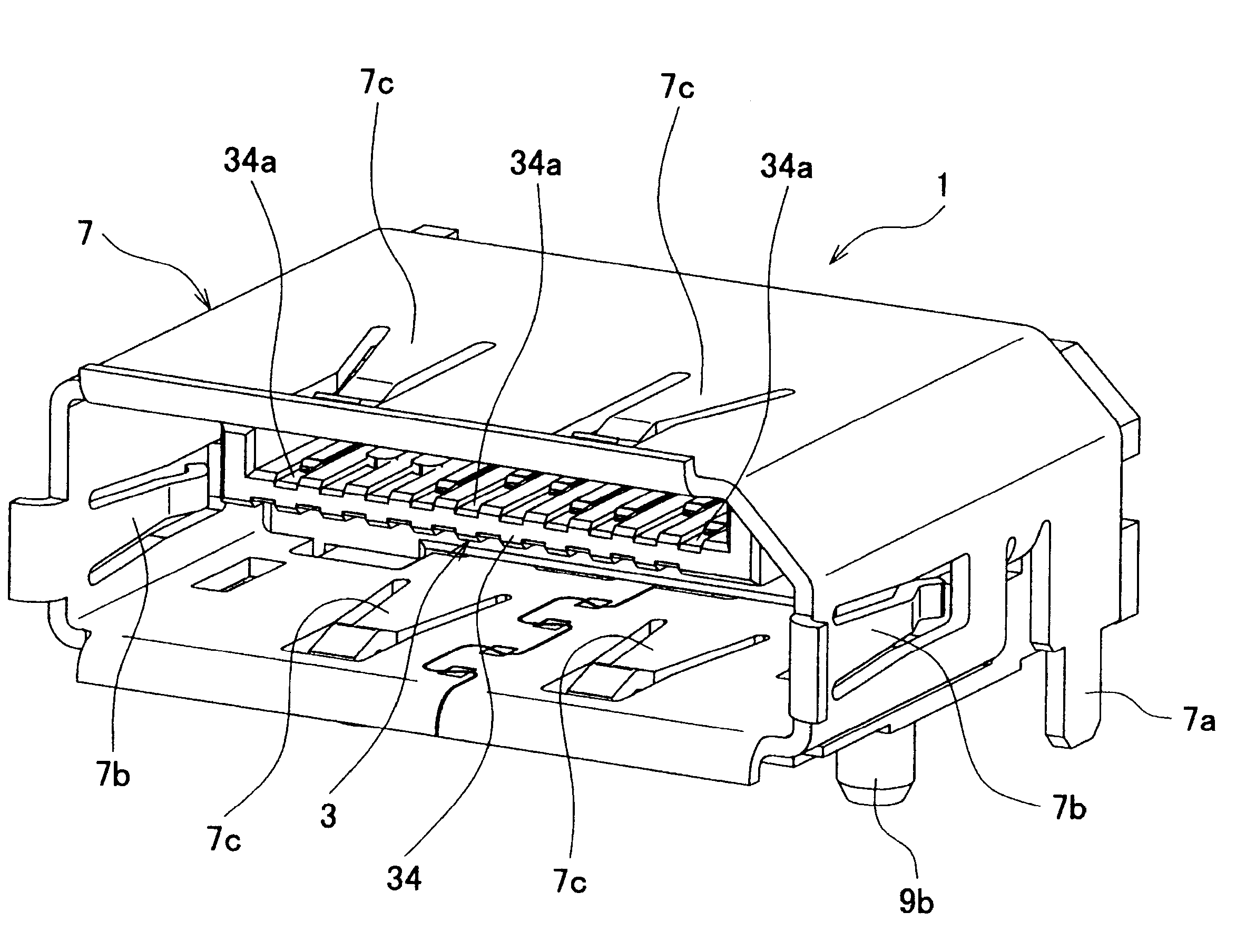
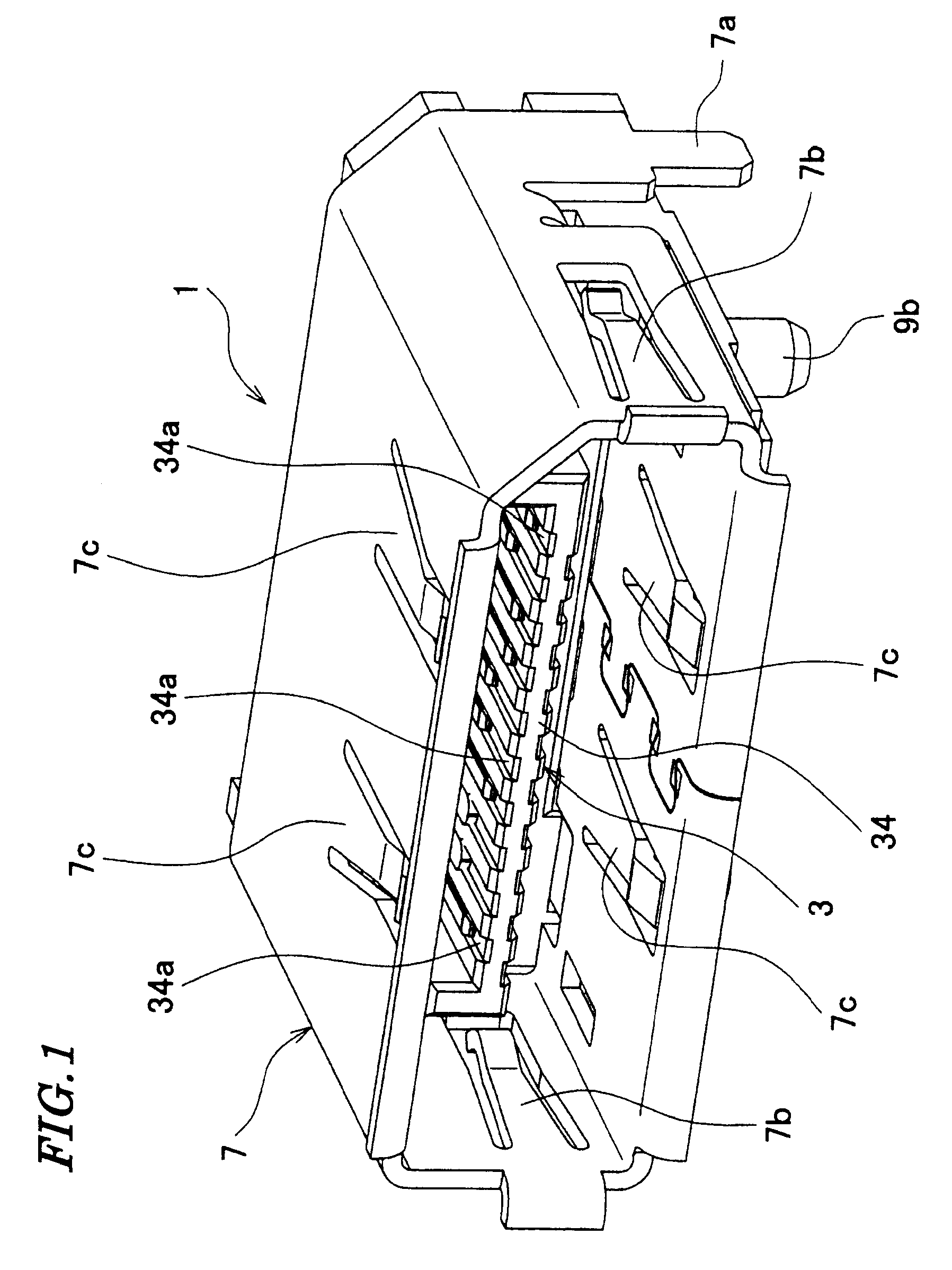
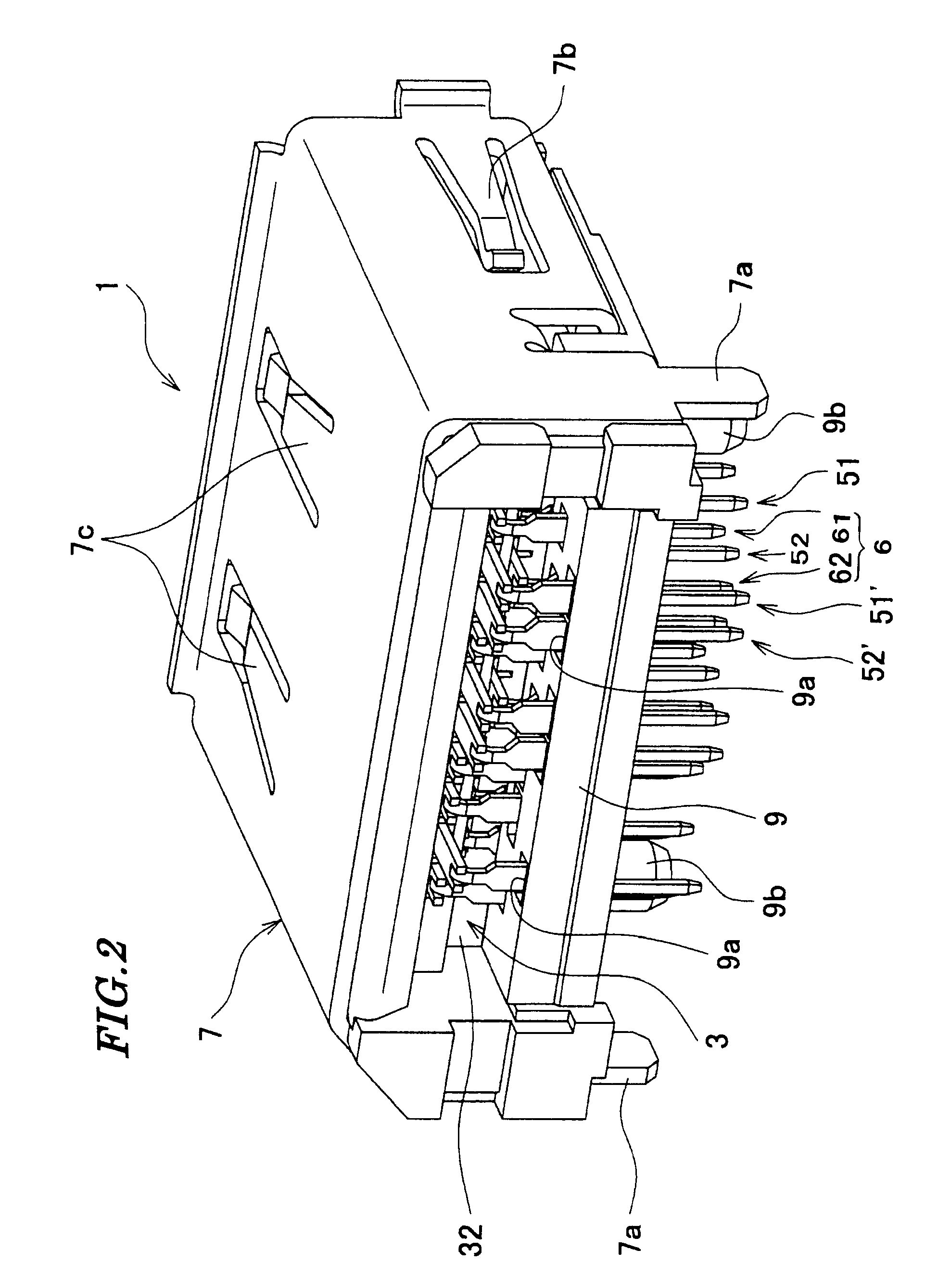
[0032]Referring to FIGS. 1 and 2, a connector 1 according to the present invention is comprised of a housing 3, a plurality of pairs of signal contacts 5 (see FIGS. 6 and 7), ground contacts 6 (see FIGS. 2 and 3), and a locator 9.

[0033]The housing 3 is made of e.g. resin. As shown in FIGS. 2 to 4, the housing 3 includes a bottom board portion 31, a rear wall portion 32, and a holding portion 34. The upper and lower sides of the connector 1 as viewed in FIG. 4 are the front and rear of the same, respectively, and the left and right sides of the connector 1 as viewed in FIG. 5 are the front and rear of the same, respectively. The bottom board portion 31 is plate-shaped. The rear wall portion 32 is continuous with a rear portion of the bottom board portion 31. The rear wall portion 32 is formed with a plurality of through holes (not shown) therein at predetermined spaced intervals. The through holes are communicated with grooves 34a, referred to hereinafter, of the holding portion 34. ...

second embodiment

[0050]Next, a description will be given of a connector according to the present invention with reference to FIG. 10.

[0051]Component parts identical to those of the connector according to the first embodiment are designated by identical reference numerals, and detailed description thereof is omitted, while only essential component parts different in construction from those of the first embodiment will be described hereinafter.

[0052]In the second embodiment, the first terminal portion groups T1 and the second terminal portion groups T2 are arranged along the arranging direction A in an alternating manner, the first and second terminal portions 51d and 52d of the first terminal portion groups T1 and the terminal portions 62d of the second terminal portion groups T2 are arranged in substantially the same straight line, and the first and second terminal portions 51d′ and 52d′ of the second terminal portion groups T2 and the terminal portions 61d of the first terminal portion groups T1 ar...


PUM


Abstract

A connector capable of suppressing crosstalk between adjacent different pairs of signal lines on a printed circuit board, and facilitating impedance matching. The connector includes first signal contacts each including a signal terminal portion, second signal contacts each including a signal terminal portion, first ground contacts each including bifurcated terminal portions, second ground contacts each including a terminal portion, and a housing which holds these contacts. Each signal terminal portion, bifurcated terminal portion and terminal portion are mounted on a printed circuit board. Virtual lines connecting terminal portions forming each first terminal portion group form a quadrangle. Virtual lines connecting terminal portions forming each second terminal portion group form a triangle. The first and second terminal portion groups are arranged along a predetermined direction in an alternating manner.

Description

BACKGROUND OF THE INVENTION[0001]1. Field of the Invention[0002]This invention relates to a connector, and more particularly to a connector for differential signal transmission.[0003]2. Description of the Related Art[0004]Conventionally, there has been proposed a connector for high-speed differential signal transmission, comprised of signal contacts, ground contacts, and a housing which holds the contacts (see Japanese Patent No. 3564555).[0005]The signal contacts include plus signal contacts and minus signal contacts, each plus signal contact and each minus signal contact forming a pair. The plus signal contact and the minus signal contact, forming each pair, are disposed at adjacent to each other.[0006]The plus signal contact, the minus signal contact, and the ground contact each include a terminal portion which is inserted through an associated one of through holes of a printed circuit board.[0007]The terminal portions of the plus signal contacts, the minus signal contacts, and t...

Claims


Application Information

Patent Timeline
IPC IPC(8): H01R24/00H01R13/6471H01R13/6474H01R13/658H01R13/6594
CPCH01R13/65802H01R13/6471H01R12/724Y10S439/941H01R13/6473H01R13/6582
Inventor OYAKE, TAKAYOSHIYOKOYAMA, YOHEI
Owner JAPAN AVIATION ELECTRONICS IND LTD
Why Eureka
Try Eureka