
Control of uplink transmit power

a technology of transmit power and control, applied in the field of wireless communication, can solve the problems of interference between adjacent frequency bands, increase the cost of communication services, and reduce the efficiency of spectrum utilization

Inactive Publication Date: 2010-10-07
LG ELECTRONICS INC
View PDF12 Cites 181 Cited by
  • Summary
  • Abstract
  • Description
  • Claims
  • Application Information

AI Technical Summary

Benefits of technology

[0017]In another aspect, a transmitter includes a transmit circuitry to transmit a transmit signal, a power controller configured to determine a MPR based on resource allocation, adjust a maximum output power by using the MPR, and determine a transmit power of the transmit signal within the adjusted maximum output power, wherein the resource allocation comprises a number of contiguous resource blocks in a channel bandwidth and a starting index which is an index of a resour

Problems solved by technology

The proliferation of wireless communication systems has created system interoperability problems, degrades efficiency of spectrum utilization, and increases the cost of communication services.
Spurious emissions are emissions which are caused by unwanted transmitter effects such as harmonics emission, parasitic emissions, intermodulation products and frequency conversion products.
The spurious emissions may cause interference between adjacent frequency bands.
In the adjacent E-UTRA band, the spurious emissions by a transmitter may cause interference with the other system's frequency band.
When an E-UTRA band is adjacent to the PSB, the interference due to the spurious emissions may be caused.

Method used


Image

  • Control of uplink transmit power
  • Control of uplink transmit power
  • Control of uplink transmit power

Examples


Embodiment Construction

[0030]The technique, method and apparatus described below can be used in various wireless access technologies such as code division multiple access (CDMA), frequency division multiple access (FDMA), time division multiple access (TDMA), orthogonal frequency division multiple access (OFDMA), single carrier frequency division multiple access (SC-FDMA), etc. The wireless access technologies can be implemented with various wireless communication standard systems. CDMA may be implemented with a radio technology such as Universal Terrestrial Radio Access (UTRA) or CDMA2000. TDMA may be implemented with a radio technology such as Global System for Mobile communications (GSM) / General Packet Radio Service (GPRS) / Enhanced Data Rates for GSM Evolution (EDGE). OFDMA may be implemented with a radio technology such as IEEE 802.11 (Wi-Fi), IEEE 802.16 (WiMAX), IEEE 802-20, E-UTRA (Evolved-UTRA) etc. 3rd generation partnership project (3GPP) long term evolution (LTE) is a part of an evolved-univers...


PUM


Abstract

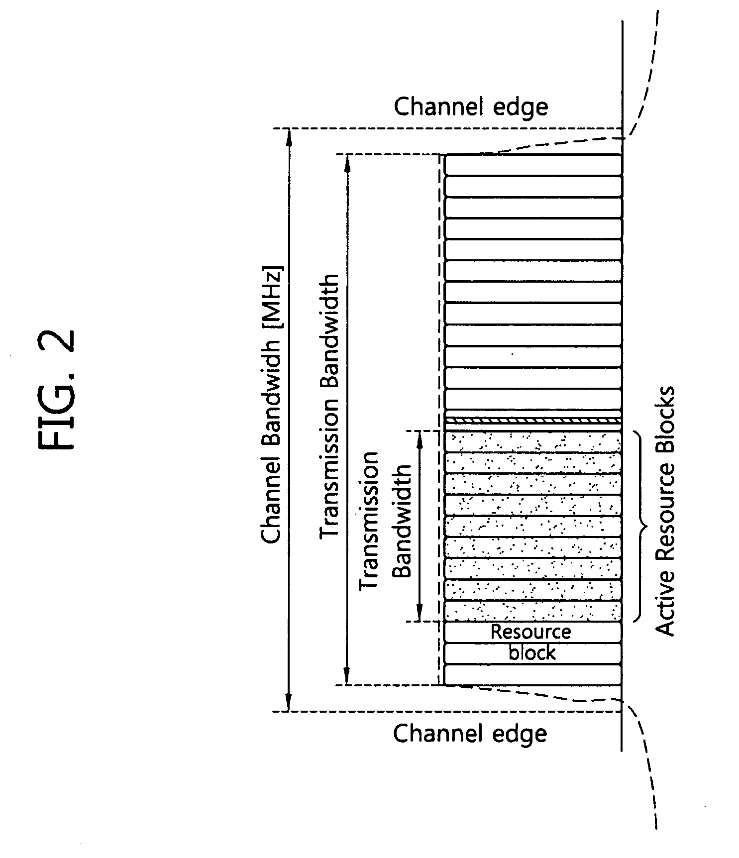
A method and apparatus of controlling an uplink transmit power are provided. A maximum power reduction (MPR) is determined based on resource allocation. The resource allocation comprises a number of contiguous resource blocks in a channel bandwidth which is divided into a first region, a second region and a third region. The MPR is determined according to the number of the contiguous resource blocks in the first region and the third region, and the MPR is determined according to the starting index in the second region. The MPR in the third region increases as the number of the contiguous resource blocks decreases.

Description

BACKGROUND[0001]1. Field of the Invention[0002]The present invention relates to wireless communication and, more particularly, to an apparatus and method for controlling an uplink transmit power in a wireless communication system.[0003]2. Related Art[0004]Wireless communication systems are widely spread all over the world to provide various types of communication services such as voice or data. In general, the wireless communication system is a multiple access system capable of supporting communication with multiple users by sharing available system resources (e.g., bandwidth, transmit (Tx) power, etc.). Examples of the multiple access system include a code division multiple access (CDMA) system, a frequency division multiple access (FDMA) system, a time division multiple access (TDMA) system, an orthogonal frequency division multiple access (OFDMA) system, a single carrier frequency division multiple access (SC-FDMA) system, etc.[0005]The proliferation of wireless communication sys...

Claims


Application Information

Patent Timeline
IPC IPC(8): H04B7/00
CPCH04W52/146Y02B60/50H04W52/367
Inventor LEE, CHI HUNCHO, YONG SANG
Owner LG ELECTRONICS INC
Learn More