Vehicle seat

Inactive Publication Date: 2010-10-14
TOYOTA BOSHOKU KK
View PDF13 Cites 43 Cited by
  • Summary
  • Abstract
  • Description
  • Claims
  • Application Information

AI Technical Summary

Benefits of technology

[0024]In the vehicle seat according to the first aspect of the invention, the positional relationship of the tuber of ischium of the seated person relative to the seat cushion when the seat back and the seat cushion are in the first positions and the positional relationship of the tuber of ischium of the seated person relative to the seat cushion when the seat back and the seat cushion are in the second positions may be determined by correcting the position of the tuber of ischium of the seated person in view of the amounts of deformation of the seat cushion and the seat back due to a load applied from the seated person.
[0025]In the vehicle seat as described above, the positional relationship of the tuber of ischium of the seated person relative to the seat cushion when the seat back and the seat cushion are in the normal positions and in second positions is determined by correcting the position of the tuber of ischium of the seated person in view of the amounts of deformation of the seat cushion and the seat back due to the load applied from the seated person. When the positions of the seat cushion and the seat back are changed from those of the first positions to those of the second position, the posture of the seated person relative to the seat cushion and the seat back changes, causing variations in the magnitudes of the loads applied from the seated person to the seat cushion and seat back and the directions in which the loads are applied. Due to the variations in the amounts of deformation of the seat cushion and the seat back, the ischial contact point is displaced or shifted by an amount corresponding to the amounts of deformation. Therefore, the position of the tuber of ischium of the seated person relative to the seat cushion is corrected in view of the amounts of deformation of the s

Problems solved by technology

However, if the movement of the back contact point on the seat back between the normal position and the reclining position is observed with reference to the hip point, the seat of JP-A-7-327768 is arranged only to reduce the back displacement, but still canno

Method used


Image

  • Vehicle seat
  • Vehicle seat
  • Vehicle seat

Examples


first embodiment

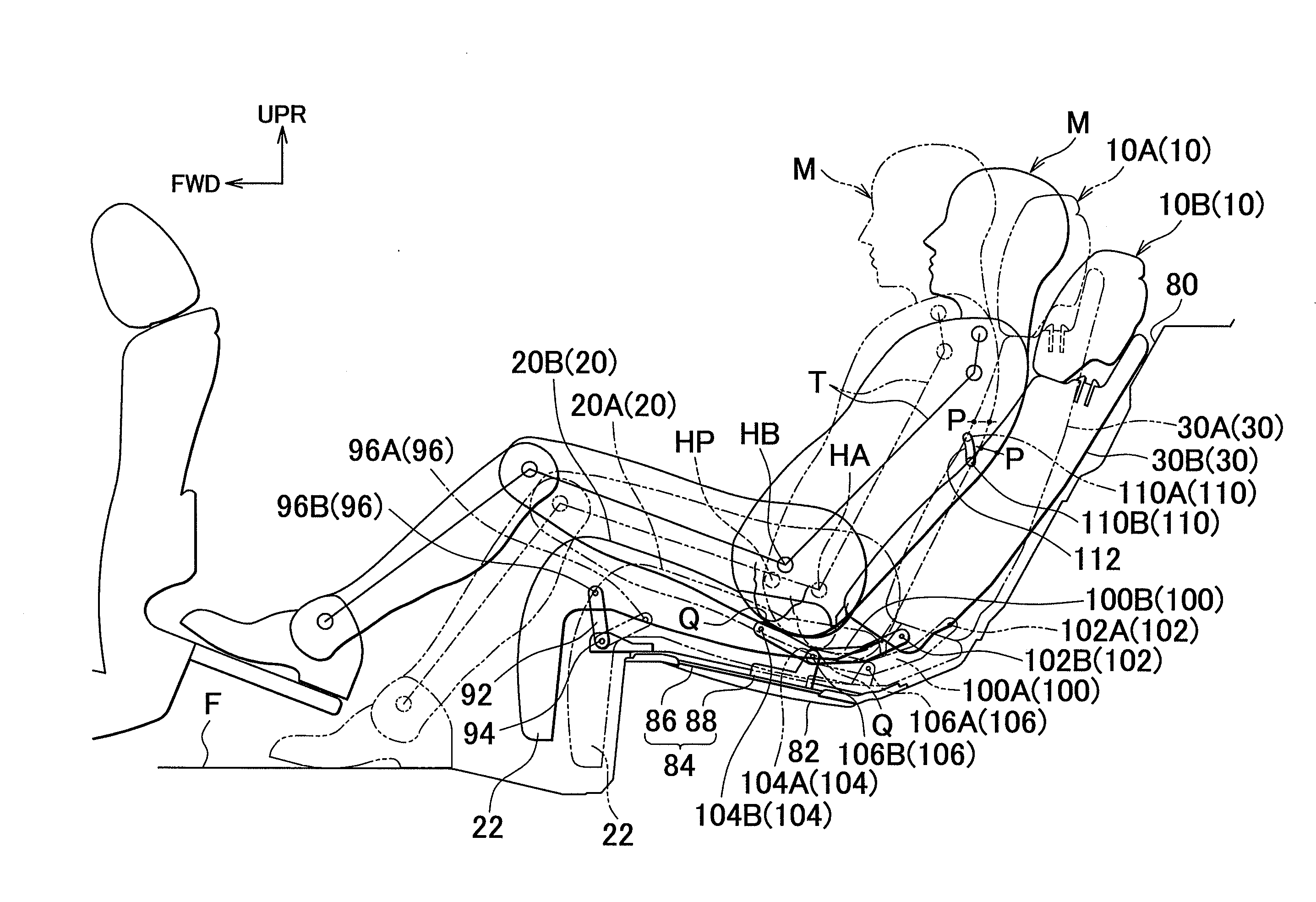
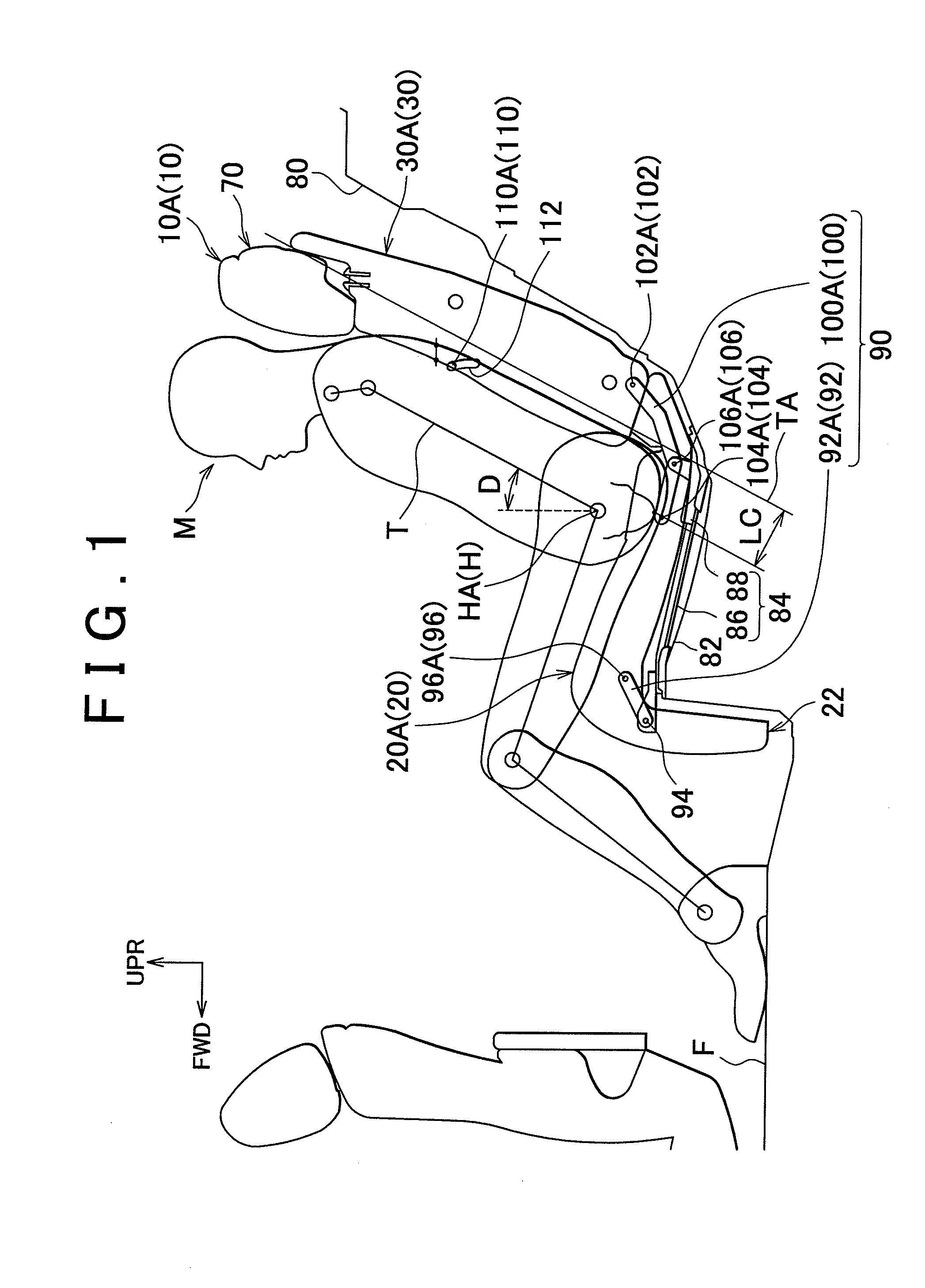
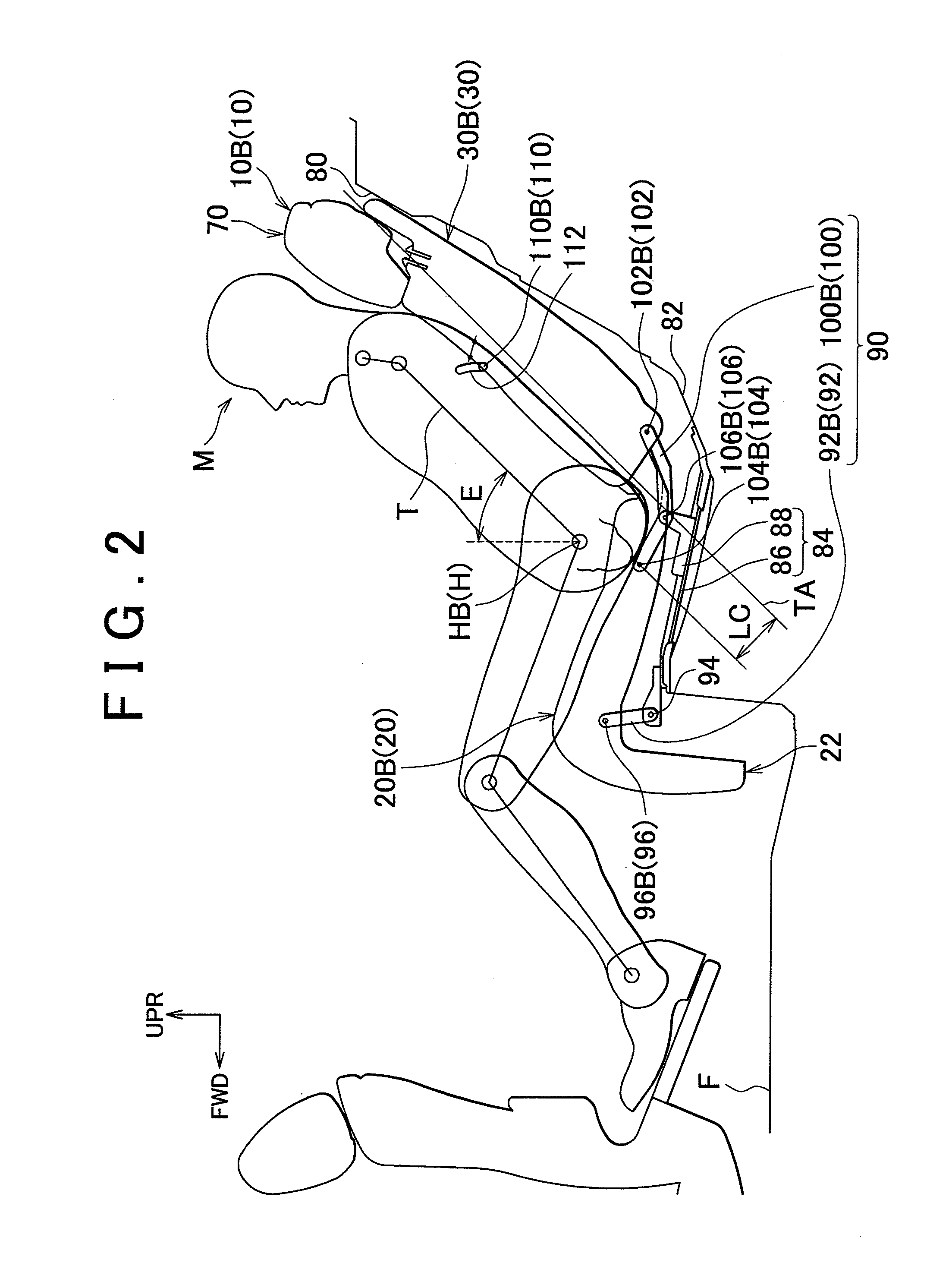
[0045]As shown in FIG. 1, the normal position 10A may be regarded as the above-mentioned “first position” of the invention. When the vehicle seat 10 is in the normal position 10A, the angle D between the seated person M (or the seat back 30) and the vertical is 28 degrees. In the normal position 10A as shown in FIG. 1, the seat back 30 is in a seat-back normal position 30A, and the seat cushion 20 is in a seat-cushion normal position 20A. Also, the hip point of the seated person M seated in the vehicle seat 10 in the normal position 10A is denoted as “hip point HA” in FIG. 1. As shown in FIG. 2, the reclining position 10B may be regarded as the above-mentioned “second position” of the invention. When the vehicle seat 10 is in the reclining position 10B, the angle E between the seated person M (or the seat back 30) and the vertical is 45 degrees. In the reclining position 10B as shown in FIG. 2, the seat back 30 is in a seat-back reclining position 30B, and the seat cushion 20 is in ...

second embodiment

[0069]In the second embodiment, the three-point link 120 is formed from a strip-like metallic member that projects in three radial directions and has three pivot points. The three-point link 120 is pivotably attached to the vehicle floor F such that the link 120 can pivot about a vehicle-floor pivot point 126 as one of the three pivot points. The three-point link 120 is also pivotably attached to a rear end portion of the seat cushion 20 such that the link 120 can pivot about a seat-cushion rear-end pivot point 124 as one of the remaining two pivot points which is located closer to the rear of the vehicle. The three-point link 120 is also pivotably attached to a lower end portion of the skeleton framework of the seat back 30 such that the link 120 can pivot about a seat-back pivot point 122 located closer to the front of the vehicle, as the remaining pivot point.

[0070]The operation of the vehicle seat 210 constructed as described above according to the second embodiment will be desc...

third embodiment

[0105]According to the modified example of the third embodiment, the position of the tuber-of-ischium point of the seated person M relative to the seat cushion 320 is corrected in view of the amounts of deformation of the seat cushion 320 and the seat back 330 due to the load applied from the seated person M, so that the “back displacement” and “hip displacement” of the seated person M can be eliminated with further reliability.

[0106]The vehicle seat of the invention is not limited to those of the illustrated embodiments, but various changes, additions and / or deletions may be made without changing the principle of the invention. While the link mechanism 90 is operated manually in the first through third embodiments, the invention is not limited to this arrangement. For example, the link mechanism 90 may be replaced by a link mechanism that is electrically operated.

[0107]While the link mechanism 90 is operated manually in the first through third embodiments, the invention is not limi...


PUM


Abstract

In a vehicle seat having a seat back and a seat cushion that are placed in one of a normal position and a reclining position that is more reclined than the normal position, a link mechanism is operable to change the positions of the seat back and the seat cushion by moving the seat back and the seat cushion in relation to each other, so that a back contact point of the seat back, where a predetermined portion of the back of the seated person contacts the seat back, contacts the predetermined portion of the back of the seated person in both the normal position and the reclining position, and so that an ischial contact point of the seat cushion, where a tuber-of-ischium of the seated person contacts the seat cushion, contacts the tuber-of-ischium of the seated person in both the normal position and the reclining position.

Description

INCORPORATION BY REFERENCE[0001]The disclosure of Japanese Patent Application No. 2009-96128 filed on Apr. 10, 2009 including the specification, drawings and abstract is incorporated herein by reference in its entirety.BACKGROUND OF THE INVENTION[0002]1. Field of the Invention[0003]The invention relates to a vehicle seat.[0004]2. Description of the Related Art[0005]FIG. 8 is a schematic view useful for explaining the reclining motion of a known vehicle seat 510. In FIG. 8, constituent elements of the vehicle seat 510 are illustrated in simplified forms, and the construction of the seat 510 is partially omitted. As shown in FIG. 8, the vehicle seat 510 is provided as a rear seat in the second row or third row in the vehicle compartment, and consists principally of a seat back 530 and a seat cushion 520. The seat back 530 of the vehicle seat 510 is mounted along a vehicle-body wall 580 formed as a part of a vehicle-body structure, such as a luggage compartment, and the seat cushion 52...

Claims


Application Information

Patent Timeline
IPC IPC(8): B60N2/66
CPCB60N2/2209
Inventor KUNO, SATORU
Owner TOYOTA BOSHOKU KK
Why Eureka
Try Eureka