Device for detecting and locating electric discharges in fluid-insulated electrical equipment

a technology of electrical equipment and fluid insulation, which is applied in the direction of fault location, dielectric strength testing, instruments, etc., can solve the problems of electrical equipment damage total, electrical equipment damage, and sensor needs to be provided

Inactive Publication Date: 2010-10-14
ALSTOM TECH LTD
View PDF9 Cites 29 Cited by
  • Summary
  • Abstract
  • Description
  • Claims
  • Application Information

AI Technical Summary

Benefits of technology

[0018]Another object of the invention is to provide a device for detecting and locating at least one electric discharge in fluid-insulated electrical equipment that provides a high level of safety for the operator called on to use the device.
[0019]Yet another object of the invention is to be able to detect and locate electric discharges while being little affected by the noise that inevitably exists.
[0025]In a variant, the main grounding line segment may be electrically discontinuous between the first and second ends of the secondary grounding line segment, in this way, the current detector measures a current of greater intensity that in the preceding variant, thereby enabling discharges of smaller intensity to be detected.
[0027]The signals delivered by the current detectors may be integrated. For a Rogowski sensor in which the output signal is proportional to the time derivative of the current, integration makes it possible to obtain the current.

Problems solved by technology

In order to protect electrical equipment of that type, attempts are made to detect and locate electric discharges in order to eliminate the source thereof, since such discharges run the risk of damaging the electrical equipment in the shorter or longer term.
If partial discharges lead to a total strike they can give rise to the electrical equipment being damaged totally.
The drawback with those methods is that the sensors need to be provided when the equipment is designed and built.
The drawback of that configuration is that it is necessary to provide the inspection windows, even though inspection windows are being used less and less in metal-housing high-voltage electrical units.
That configuration is becoming less and less applicable, since dielectric cones are no longer used to prevent direct electrical connections being made between fastening flanges terminating two consecutive compartments.
In both of the above two circumstances, it is necessary to be able to access the conductor under voltage on its own, i.e. without the conductive housing, and that is not possible in a substation that is in operation.
Furthermore, the housing is large in diameter, thereby making it difficult to construct Rogowski coils of such a size.

Method used


Image

  • Device for detecting and locating electric discharges in fluid-insulated electrical equipment
  • Device for detecting and locating electric discharges in fluid-insulated electrical equipment
  • Device for detecting and locating electric discharges in fluid-insulated electrical equipment

Examples


Embodiment Construction

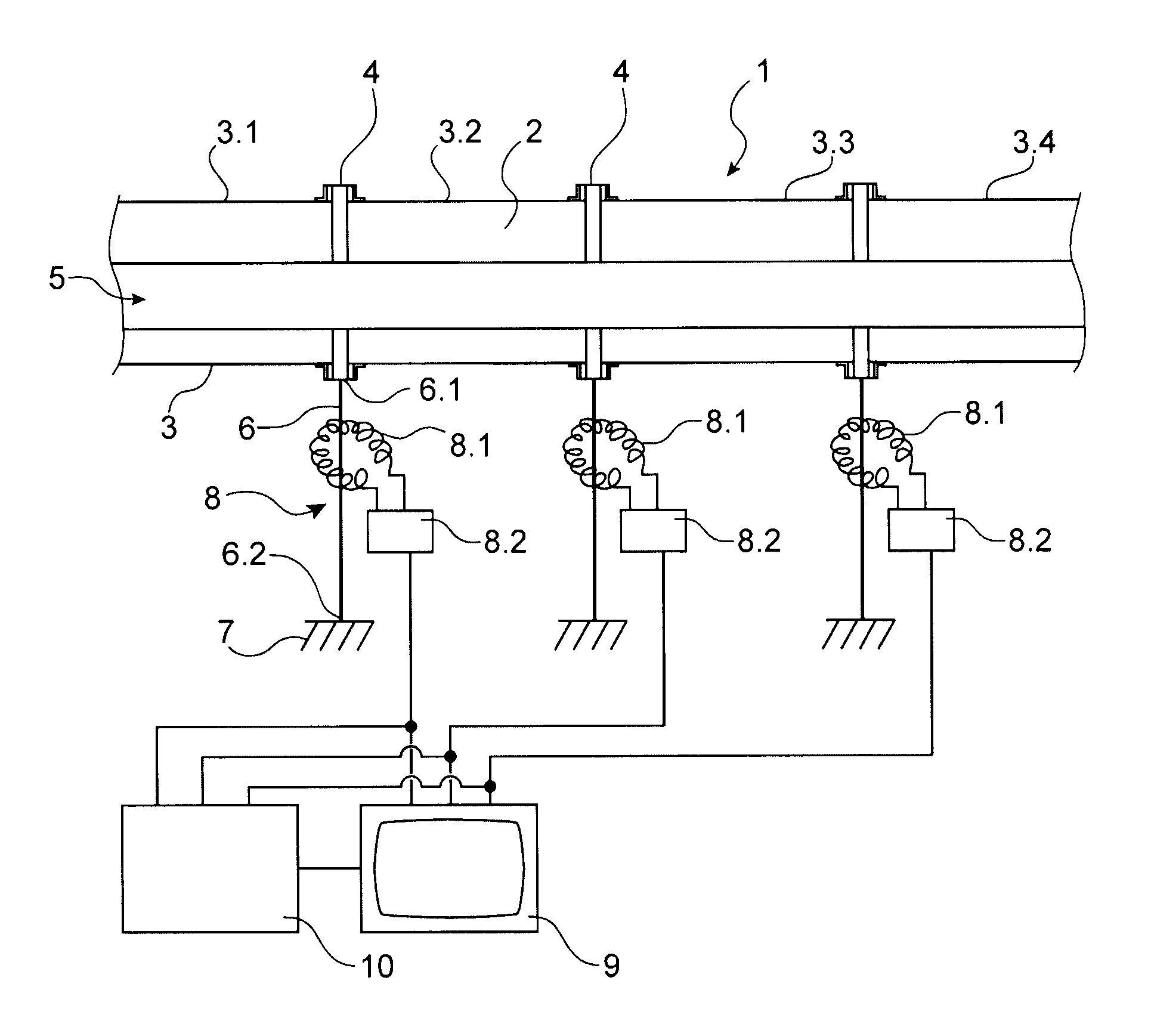
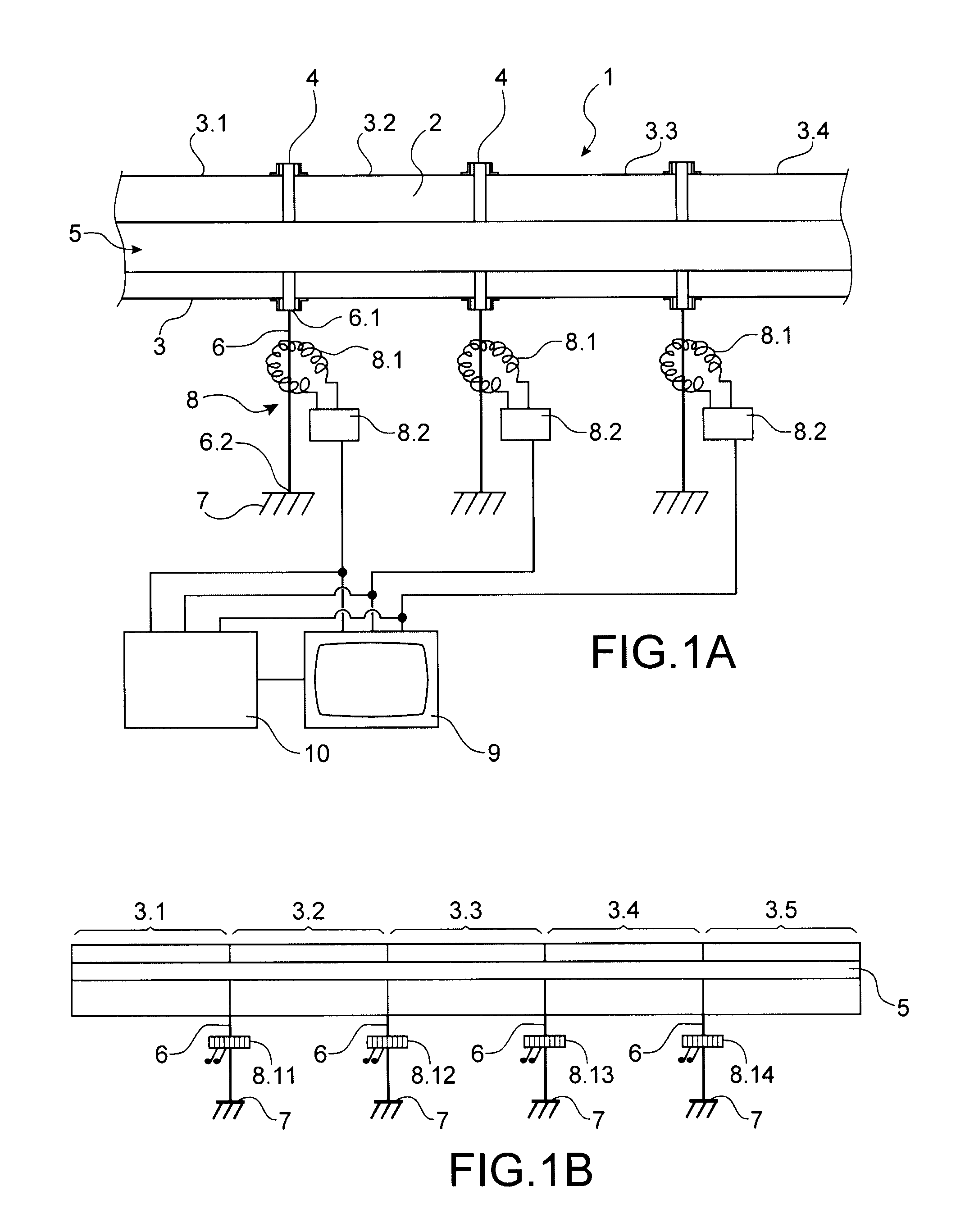
[0044]Reference is made to highly diagrammatic FIG. 1A, which shows electrical equipment 1 insulated by fluid 2 contained in electrically-conductive housing 3. In the example described, the electrically-conductive housing 3 is in the form of a tube, and it is made up of a plurality of tubular compartments 3.1, 3.2, 3.3, 3.4 that are assembled to one another, e.g. by flanges 4. The various compartments 3.1, 3.2, 3.3, 3.4 are not necessarily assembled to one another in linear manner. There is no electrical insulation between two successive compartments. The fluid 2 contained in the housing 3 may be sulfur hexafluoride SF6. An electrical conductor element 5 is immersed therein, which element may have a very variety of forms: it may be a bar, switchgear such as a disconnector or a circuit breaker, a transformer, or else. This electrical conductor elements 5 may be held in place within the housing 3 with the help of dielectric cones (not shown).

[0045]The electrical equipment 1 is provide...


PUM


Abstract

A device for detecting and locating at least one electric discharge in equipment insulated by fluid contained in an electrically-conductive housing. The equipment includes a plurality of grounding lines connected between the housing and ground. The device includes a plurality of Rogowski coil type current detectors and a mechanism synchronously comparing signals delivered by the current detectors. The coil of each detector is placed around a respective one of the lines. Each detector delivers a signal representative of current flowing in the line, with occurrence of an electric discharge giving rise to a sudden variation in the current, and with electric discharge being located within an inside zone of the housing situated in proximity of the line that is surrounded by the detector that was first to deliver the sudden variation of current.

Description

TECHNICAL FIELD[0001]The present invention relates to a device for detecting and locating at least one electric discharge in fluid-insulated electrical equipment.[0002]By way of example, the fluid-insulated electrical equipment in question may be constituted by a metal-housing high voltage electrical unit of the kind known as gas-insulated switchgear (GIS). It is possible to consider that the fluid-insulated electrical equipment is a transformer located in a tank filled with a dielectric liquid, or a segment of a set of gas-insulated bars.[0003]Metal-housing units or gas-insulated switchgear comprise tight electrically-conductive housing containing at least one conductor element that is raised to a high voltage. The housing is filled with an insulating gas such as sulfur hexafluoride. The housing is connected to ground potential in order to ensure safety for personnel working in the vicinity of such electrical equipment. For this purpose, at least one grounding line connects the hou...

Claims


Application Information

Patent Timeline
Patent Type & Authority Applications(United States)
IPC IPC(8): G01R31/08
CPCH01H33/26G01R31/1254
Inventor GRIESHABER, WOLFGANGFANGET, ALAIN
Owner ALSTOM TECH LTD
Why Eureka
Try Eureka