AI technical title is built by PatSnap AI team. It summarizes the technical point description of the patent document.
a sleep apnea monitor and portable technology, applied in the field of monitoring sleep apnea, can solve the problems of unreliable units, interfere with normal family life, and not help sufferers in the home setting, and achieve the effect of light weigh
Inactive Publication Date: 2010-10-14
INVENTION DYNAMICS
View PDF10 Cites 11 Cited by
Summary
Abstract
Description
Claims
Application Information
AI Technical Summary
This helps you quickly interpret patents by identifying the three key elements:
Problems solved by technology
Method used
Benefits of technology
Benefits of technology
[0045]The primary objective of the present invention is to come up with a sleep apnea monitor that is light in weight, comfortable to wear at night and does not come in the way of normal family life.
[0046]Another objective of the present invention is to increase the reliability of the unit by reducing the number of moving parts.
[0047]A third objective of the present invention is to bring down the cost of manufacture through the use of minimal as well as less expensive parts so that the unit is affordable for the vast majority of patients.
Problems solved by technology
This is a diagnostic method which does not help the sufferer in a home setting.
This is not a preferred method since it is inconvenient for the patient and interferes with normal family life.
The unit can easily get out of alignment after a brief period of use and so become useless.
Too sensitive an instrument not only costs more, it can give false readings because of extraneous “noise”.
The strain gauges also increase the cost of the unit.
All the units that use an elastic belt to mount the sensor have another common drawback.
In daily use, the elasticity of the belt can weaken and become useless.
Since the initial pressure itself can vary every time the belt is worn, finding acceptable pressure variation to activate the alarms will be complicated.
Also the cost of the pressure transducer is relatively high.
This will be irritating to the wearer.
Also, it uses a lot of mechanical parts.
Although the inventor specifies material to be used to reduce friction, there will still be considerable friction that the intended result will not be achieved in reality.
The increase in the number of parts also increases the cost of manufacture.
The unit is complicated and not reliable.
When a person lies on his back, the casing will cause discomfort.
The signal generators are also not of the simple type, thus adding to the cost and complexity.
Method used
Image
Click on the blue label to locate the original text in one second.
Reading with bidirectional positioning of images and text.
Examples
Embodiment Construction
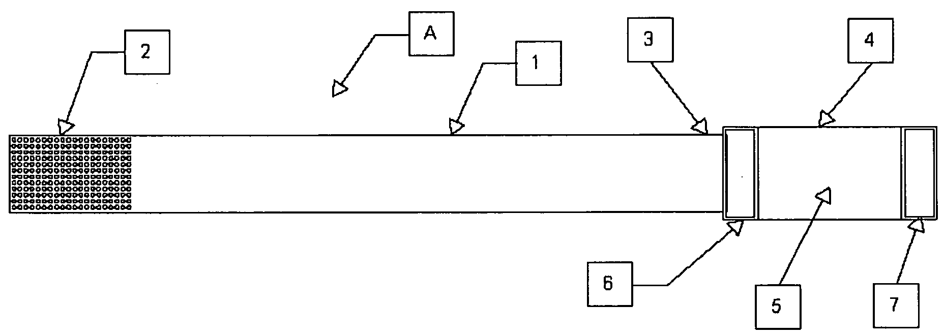
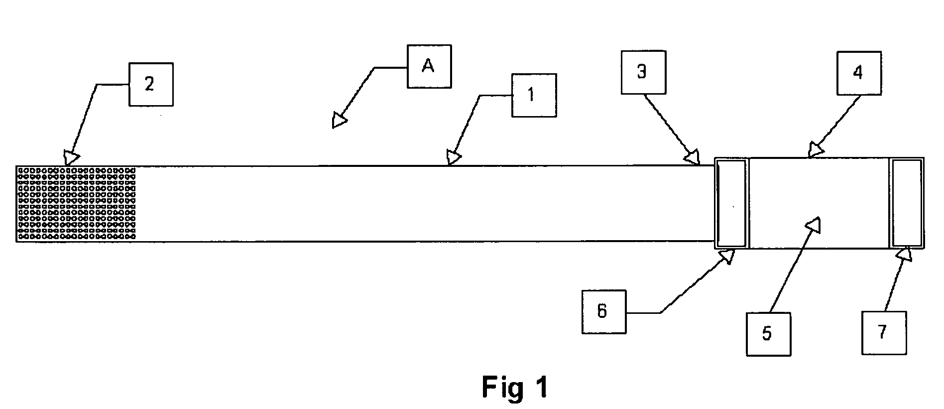
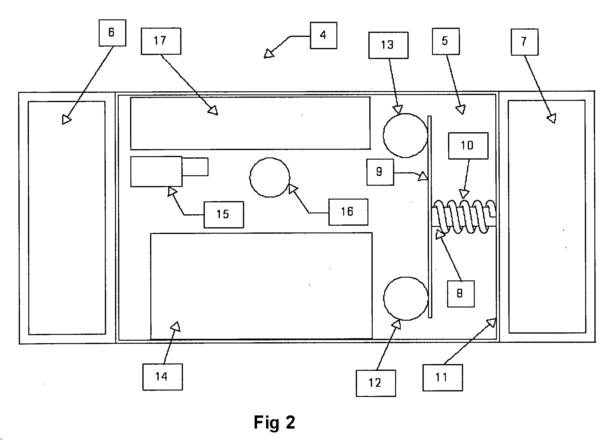
[0061]FIG. 1 refers to a preferred embodiment of the present invention. Here, a belt-sensor unit, generally referred to as A, has a belt 1, attached to a buckle assembly 4. The buckle assembly has a buckle 5, inside which are located a sensor, an evaluator, a vibrator, an alarm unit and a rechargeable battery. These will be explained further while describing FIG. 2 and FIG. 3. On one side of buckle 5, is a slot 6, which is fixedly attached to the buckle. On the other side of buckle 5 is another slot 7, which is movably attached to the buckle. Slot 6 and slot 7 can be of any shape—circular, square, rectangular etc. as long as the belt means can pass through the opening in slot 6 and slot 7.
[0062]Belt 1 is made from a substantially non-elastic, flexible material. One end of belt 1 that is distal to the buckle assembly has a hook and loop fastener. This end will henceforth be referred to as the ‘distal end’. The hook and loop fastener, more commonly known as ‘Velcro’ is numbered 2. The...
PUM
Abstract
A belt made of a substantially non-elastic, flexible material with a buckle assembly having a sensor to sense breathing by means of the movement of the abdomen, an evaluator to use the information from the sensor to determine the occurrence of an apnea event, a vibrator motor to stimulate the wearer when an apnea event occurs, an alarm unit to alert people around the wearer should the wearer not respond to the stimuli from the vibrator motor, a rechargeable battery to power the electrical / electronics units and a data transfer port to transfer data from the evaluator to a display console. The display console is a stand-alone unit that receives data from the evaluator and displays the time of each apnea event that occurred.
Application Information
Patent Timeline
Application Date:The date an application was filed.
Publication Date:The date a patent or application was officially published.
First Publication Date:The earliest publication date of a patent with the same application number.
Issue Date:Publication date of the patent grant document.
PCT Entry Date:The Entry date of PCT National Phase.
Estimated Expiry Date:The statutory expiry date of a patent right according to the Patent Law, and it is the longest term of protection that the patent right can achieve without the termination of the patent right due to other reasons(Term extension factor has been taken into account ).
Invalid Date:Actual expiry date is based on effective date or publication date of legal transaction data of invalid patent.

