Plate fin heat exchanger

a heat exchanger and fin technology, applied in indirect heat exchangers, laminated elements, lighting and heating apparatus, etc., can solve the problems of heat conductivity reduction, heat exchange efficiency of the heat exchanger part, and heat conductivity of the fin plate b, so as to prevent further leakage, reduce the size and weight of the heat exchanger, and be easy to detect. and sure

Active Publication Date: 2010-10-21
KOBE STEEL LTD
View PDF14 Cites 29 Cited by
  • Summary
  • Abstract
  • Description
  • Claims
  • Application Information

AI Technical Summary

Benefits of technology

[0023]According to this structure, even if the fluid flows from the outermost flow passage in the arrangement direction of the flow passages of the heat exchange part into the innermost sealed space of the sensing part during the operation of the heat exchanger, the fluid detection means detects this outflow, whereby the outflow of the fluid from the flow passage can be easily and surely detected. Further, since the fluid leaked to the innermost sealed space is confined within the sealed space, the fluid can be prevented from further leaking to the outside.
[0024]Each of the sensing parts preferably has two of the sealed spaces. By providing two sealed spaces in each sensing part, the fatigue by the thermal stress based on the heat of the fluid, which is accumulated in each partition wall, can be detected without external leak of the fluid while suppressing the increase in size and weight of the heat exchanger.
[0025]According to the present invention, it is possible to provide a plate fin heat exchanger capable of preventing external leak of fluid performing the heat exchange while suppressing deterioration of performance or increase in size and weight.

Problems solved by technology

However, when the rigidity of the fin plate 104 is enhanced in this way, the heat conductivity of the fin plate 104 is reduced, whereby the heat exchange efficiency of the heat exchange part 100 is deteriorated, resulting in deterioration of performance of the heat exchanger.
The use of the reinforcing member involves a problem such as increase in size or weight of the device.

Method used


Image

  • Plate fin heat exchanger
  • Plate fin heat exchanger
  • Plate fin heat exchanger

Examples


Embodiment Construction

[0031]One preferred embodiment of the present invention will be described in reference to the accompanying drawings.

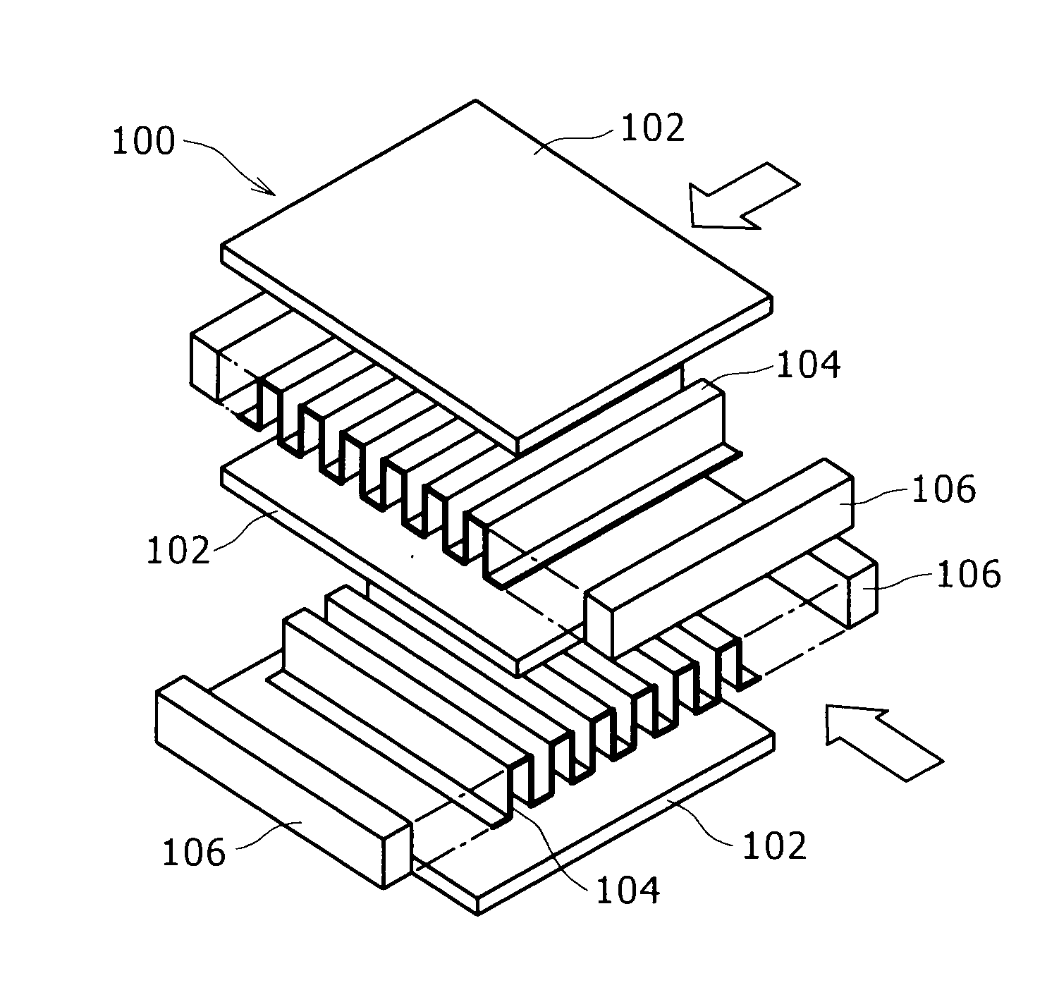
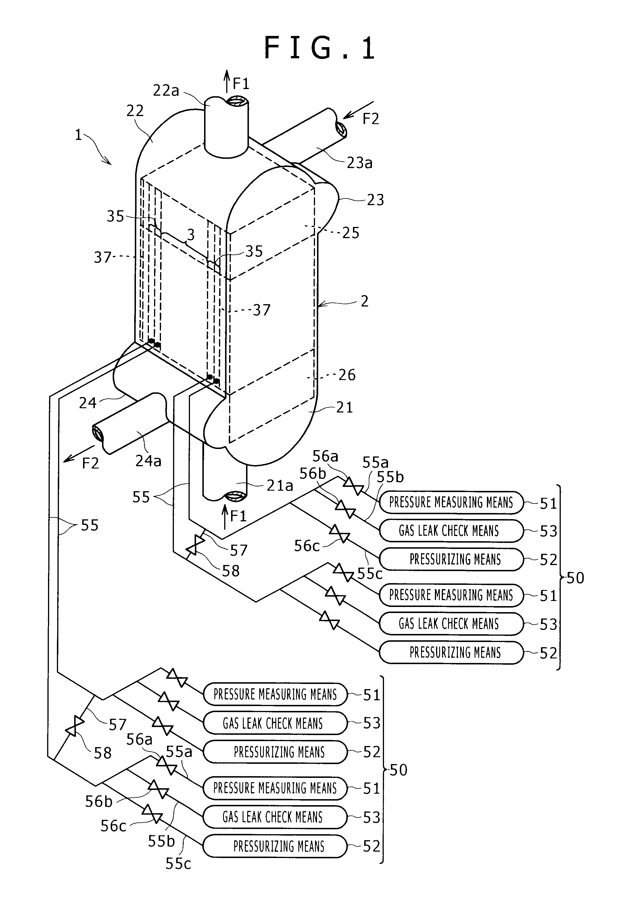
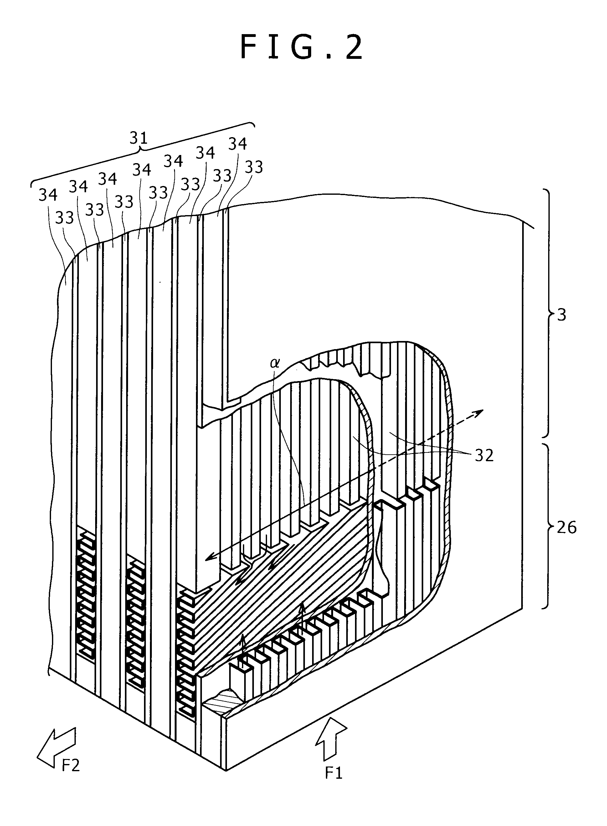
[0032]A plate fin heat exchanger (hereinafter also simply referred to as “heat exchanger”) according to the present invention is adapted to perform heat exchange between a first fluid and a second fluid both flowing therein. More specifically, as shown in FIGS. 1 to 3, a heat exchanger 1 includes a vertical box-shaped casing 2; and a heat exchange part 3 provided within the center of the casing 2, in which a first flow passage 30a for carrying a first fluid F1 and a second flow passage 30b for carrying a second fluid F2 are alternately arranged.

[0033]The casing 2 includes a bottom header 21 and a top header 22 for the first fluid provided at the bottom and at the top thereof respectively. The casing 2 further includes an upside header 23 and a downside header 24 for the second fluid provided at an upside and a downside portions thereof respectively. A first fluid inlet...


PUM


Abstract

A plate fin heat exchanger of the present invention includes a heat exchange part including a heat exchange part main body including layers of plural flow passages, and heat transfer members each of which is disposed within each flow passage of the heat exchange part main body to transfer the heat of fluid flowing in each of the flow passages to each partition walls opposed across the flow passage; and sensing parts connected to both the outsides of the heat exchange part respectively. Each of the sensing parts includes plural sealed spaces, and a sensor wall disposed to separate the outermost sealed space from the sealed space on the inner side thereof. The plate fin heat exchanger further includes a detection means for detecting damage of the sensor wall of the sensing part. According to such a structure, external leak of the fluid performing the heat exchange can be prevented while suppressing deterioration of performance or increase in size or weight.

Description

BACKGROUND OF THE INVENTION[0001]1. Field of the Invention[0002]The present invention relates to a so-called plate fin heat exchanger which is internally provided with fin plates.[0003]2. Description of the Related Art[0004]As the plate fin heat exchanger (hereinafter also simply referred to as “heat exchanger”), the one described in Japanese Patent Application Laid-Open No. 7-167580 is conventionally known. This heat exchanger includes a heat exchange part including plural flow passages for carrying first fluid and flow passages for carrying second fluid alternately arranged within a casing. Concretely, as shown in FIGS. 4A and 4B, a heat exchange part 100 includes a plurality of partition plates 102 placed in parallel at intervals; corrugated plate-like fin plates 104 each of which is placed between the partition plates 102; and sealing members 106 placed on both sides of the fin plates 104 in their width direction so as to sandwich them, the sealing members 106 sealing the space ...

Claims


Application Information

Patent Timeline
Patent Type & Authority Applications(United States)
IPC IPC(8): F28F27/00F28F3/14
CPCF28D9/0062F28F27/00F28F3/025F28D9/0093F25J5/002F25J2280/02
Inventor MITSUHASHI, KENICHIROTERADA, SUSUMUNOISHIKI, KOJI
Owner KOBE STEEL LTD
Why Eureka
Try Eureka