Microscope

a microscope and lens technology, applied in the field of microscopes, can solve the problems of affecting the accuracy of the image, so as to achieve the effect of reducing or preventing shadowing, increasing the depth of focus, and avoiding distortion

Inactive Publication Date: 2010-10-21
CARL ZEISS MICROSCOPY GMBH
View PDF4 Cites 55 Cited by
  • Summary
  • Abstract
  • Description
  • Claims
  • Application Information

AI Technical Summary

Benefits of technology

[0014]Therefore, it is the object of the invention to develop an arrangement which overcomes the above-mentioned disadvantages of the prior art. In particular, it is an object of the invention to generate a light sheet with an increased depth of focus in the image field, wherein shadowing is preferably also reduced or prevented in a simple manner.

Problems solved by technology

The waves run toward one another and interfere constructively in the area in which they overlap one another so that a light sheet is generated.
When the Bessel optics are arranged in a corresponding manner with respect to the imaging objective, this constructive interference takes place in the focus plane.
Therefore, illumination with light sheets from different directions in the focus plane is unnecessary.
However, these values can also lie outside this range because they must ultimately be adjusted relative to the desired field size and light sheet thickness.
However, use of the two slits results in light losses, and the image is darker.

Method used


Image

  • Microscope
  • Microscope
  • Microscope

Examples


Embodiment Construction

[0030]It is to be understood that the figures and descriptions of the present invention have been simplified to illustrate elements that are relevant for a clear understanding of the present invention, while eliminating, for purposes of clarity, many other elements which are conventional in this art. Those of ordinary skill in the art will recognize that other elements are desirable for implementing the present invention. However, because such elements are well known in the art, and because they do not facilitate a better understanding of the present invention, a discussion of such elements is not provided herein.

[0031]The present invention will now be described in detail on the basis of exemplary embodiments.

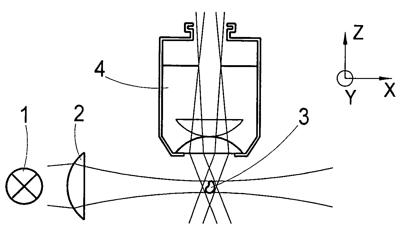
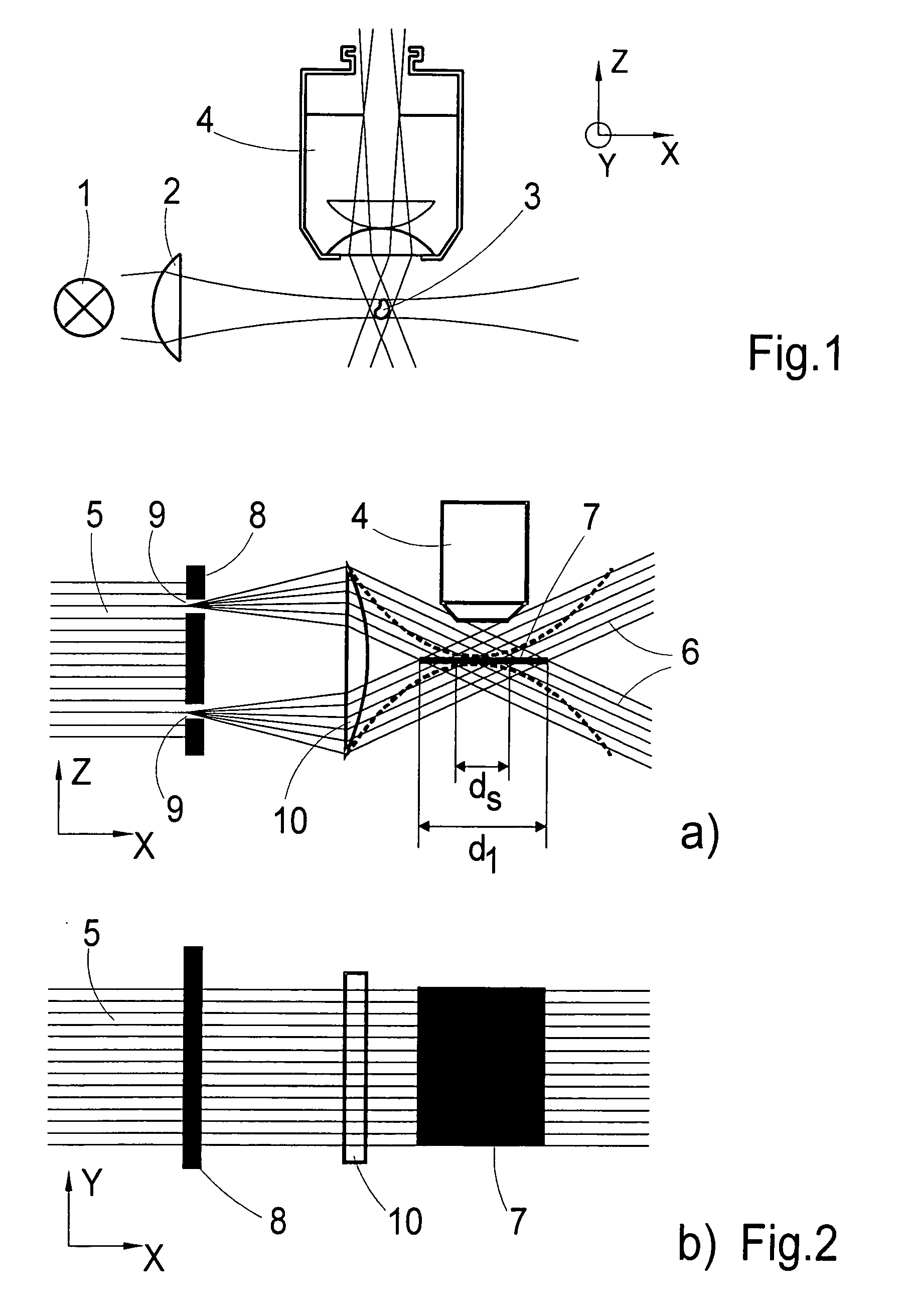
[0032]FIG. 1 shows the basic construction of a SPIM microscope. The light from an illumination source 1 is shaped by illumination optics 2 to form a light sheet and is deflected on a sample 3. The sample and the light sheet are located in the focus plane of an imaging objective...


PUM


Abstract

A microscope including an imaging objective for imaging a sample on a detector and means for illuminating the sample with a light sheet in the focus plane of the imaging objective. The illumination means includes an illumination source which emits coherent light, and Bessel optics which generate at least two plane waves from the light beam and give propagation directions for the plane waves. The propagation direction of each of the plane waves encloses an acute angle with the focus plane in each instance, the magnitude of the acute angle being identical for each of the plane waves, so that the plane waves undergo constructive interference in the focus plane so that a light sheet is generated. Similarly, the illumination means can also include an optical element by which a rotationally symmetric Bessel beam is generated from the light beam for dynamic generation of a light sheet.

Description

[0001]The present application claims priority from PCT Patent Application No. PCT / EP2008 / 010455 filed on Dec. 10, 2008, which claims priority from German Patent Application No. DE 10 2007 063 274.8 filed on Dec. 20, 2007, the disclosure of which is incorporated herein by reference in its entirety.BACKGROUND OF THE INVENTION[0002]1. Field of the Invention[0003]The invention is directed to a microscope having an imaging objective for imaging a sample on a detector and means for illuminating the sample with a light sheet in the focus plane of the imaging objective. The illumination means comprise an illumination source which emits coherent light.[0004]2. Description of Related Art[0005]A microscope in which the illumination beam path and detection beam path are arranged substantially perpendicular to one another, and in which the sample is illuminated by a light sheet in the focus plane of the imaging objective (i.e., perpendicular to its optical axis), is designed for examining sample...

Claims


Application Information

Patent Timeline
Patent Type & Authority Applications(United States)
IPC IPC(8): G02B21/06
CPCG02B21/10G02B21/06G02B27/58G02B21/16G02B26/0816G02B27/0911
Inventor LIPPERT, HELMUTWOLLESCHENSKY, RALF
Owner CARL ZEISS MICROSCOPY GMBH
Why Eureka
Try Eureka