Route computation method and system, and path computation element

a computation method and system technology, applied in the field of communication, can solve the problems of inability to determine whether the route computation can succeed, no route is available, and no route satisfies related constraints,

Inactive Publication Date: 2010-10-21
MASON LICENSING LLC
View PDF18 Cites 55 Cited by
  • Summary
  • Abstract
  • Description
  • Claims
  • Application Information

AI Technical Summary

Benefits of technology

[0035]It can be seen from the above that, through the technical solutions of the present invention that adopt the hierarchical method for sequentially computing the path segment sets, an end-to-end cross-domain path computation can be effectively performed.

Problems solved by technology

When the communication network becomes huge, management and maintenance will be difficult.
However, as each node only stores the TE information of the local domain and the reachable information of other domains but does not know the complete TE information of other domains, it becomes a problem to be solved how to compute an end-to-end path that meets all the requirements on bandwidth, switching capability, route separation, protection, and user policies in the case of multiple domains.
Because the real TE information in related domains is unavailable, it cannot be determined whether route computation can succeed from the ingress to egress until signaling flows to the corresponding domain border and triggers domain border computation.
Thus, it may frequently occur that signaling discovers during the transmission that no route is available or no route satisfies related constraints.
In addition, for this technical solution, it is difficult to compute end-to-end diverse routes (different paths with the same source and destination).
When the network is complex or large, it is difficult to manage the PCEs.
When a service passes through many domains, communication between related PCEs will be too frequent and the amount of information exchanged will be huge, which reduces the efficiency and reliability of route computation.

Method used


Image

  • Route computation method and system, and path computation element
  • Route computation method and system, and path computation element
  • Route computation method and system, and path computation element

Examples


Embodiment Construction

[0039]The route computation method and system and the PCE of the present invention are illustrated below with reference to the accompanying drawings and embodiments.

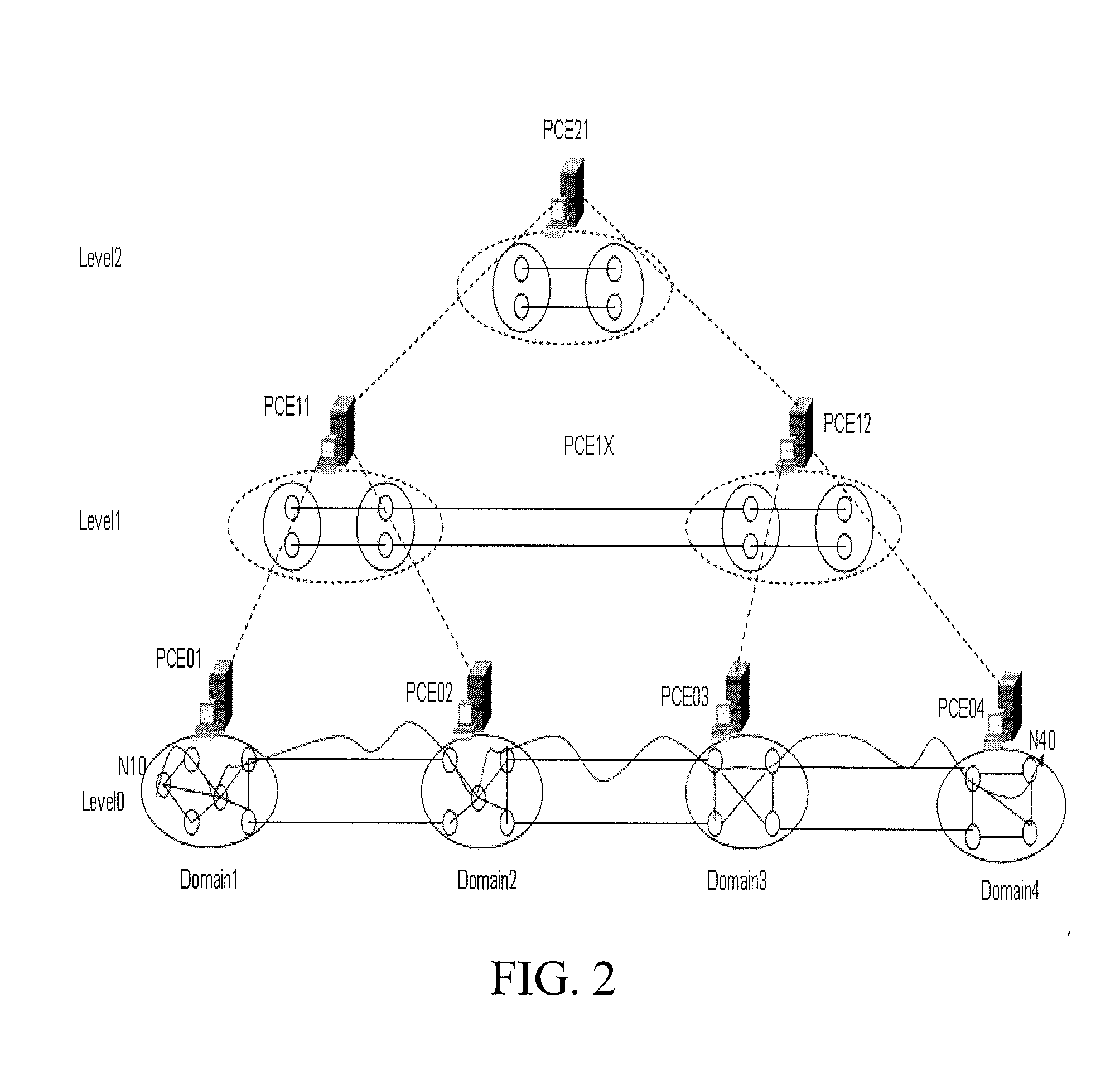
[0040]The route computation method according to embodiments of the present invention may be applied to a network structure as shown in FIG. 2. As shown in FIG. 2, the network is divided into multiple levels. When multiple domains are interconnected, for each bottom-level routing domain, one or more PCEs are directly responsible for the intra-domain routing topology and route computation of the domain; then, multiple bottom-level routing domains are directly managed by a higher-level PCE, and the higher-level PCE has inter-domain routing topologies of the bottom-level routing domains, intra-domain routes of the routing domain directly managed thereby, as well as intra-domain routing topologies of some domains based on a policy. Based on this, the entire network is managed by hierarchical abstraction based on PCEs. The num...


PUM


Abstract

A route computation method includes: receiving, by a first bottom-level PCE, a path computation command, performing a route computation on a routing domain managed thereby, obtaining and sending a path segment set with a first node to an upper-level PCE thereof; sending, by the upper-level PCE receiving the path segment set sent by a lower-level PCE, the path computation command to another lower-level PCE according to routing domains that a path to be established between the first node and a second node sequentially passes through, receiving path segment sets sent by all lower-level PCEs, and combining and sending all the received path segment sets to an upper-level PCE thereof, until a top-level PCE receives path segment sets sent by all lower-level PCEs thereof; and combining, by the top-level PCE, all the received path segment sets to generate a set of paths between the first node and the second node.

Description

CROSS-REFERENCE TO RELATED APPLICATIONS[0001]This application is a continuation of International Application No. PCT / CN2008 / 073654, filed on Dec. 22, 2008, which claims priority to Chinese Patent Application No. 200710125724.9, filed on Dec. 29, 2007, both of which are hereby incorporated by reference in their entireties.FIELD OF THE TECHNOLOGY[0002]The present invention relates to the field of communications, and more particularly to a route computation method and system, and a path computation element (PCE).BACKGROUND OF THE INVENTION[0003]A communication network is a set of geographically distributed nodes and communication links between the nodes for data transmission. The communication between nonadjacent nodes in the communication network may be realized through intermediate nodes, and this saves resources of the communication network and improves the resource utilization. Currently, various types of communication networks exist, such as synchronous digital hierarchy / synchrono...

Claims


Application Information

Patent Timeline
Patent Type & Authority Applications(United States)
IPC IPC(8): H04L12/56H04L45/42
CPCH04L45/04H04W40/02H04L45/42
Inventor DONG, JIXIONGZHANG, FATAI
Owner MASON LICENSING LLC
Why Eureka
Try Eureka