
Method and Apparatus for Measuring the Temperature of a Sheet Material

a technology of sheet material and temperature, applied in the direction of thermometers, instruments, fire alarms, etc., can solve the problems of general difficulty or inability to align the ‘square' of the thermal imaging devi

Inactive Publication Date: 2010-10-21
LAND INSTRUMENTS INTERNATIONAL
View PDF4 Cites 2 Cited by
  • Summary
  • Abstract
  • Description
  • Claims
  • Application Information

AI Technical Summary

Benefits of technology

[0018] In accordance with an embodiment of the present invention, the present invention, a method of measuring the temperature of a sheet material arranged such that the sheet material forms at least one side of a cavity so as to enhance the effective emissivity of the sheet material in the vicinity of the cavity, comprises:
[0064] Preferably, the sheet material is wound onto the roller, the roller preferably comprising a mandrel, still preferably a split mandrel of adjustable diameter for facilitating removal from the wound sheet material.

Problems solved by technology

It is generally difficult or impossible to align the thermal imaging device ‘square’ to the cavity since it would obstruct the process line.

Method used


Image

  • Method and Apparatus for Measuring the Temperature of a Sheet Material
  • Method and Apparatus for Measuring the Temperature of a Sheet Material
  • Method and Apparatus for Measuring the Temperature of a Sheet Material

Examples


Embodiment Construction

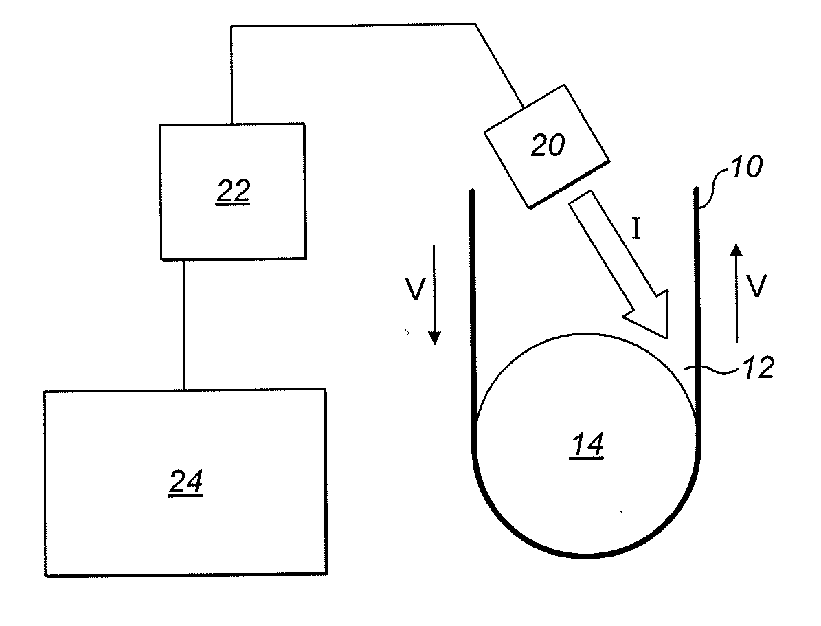
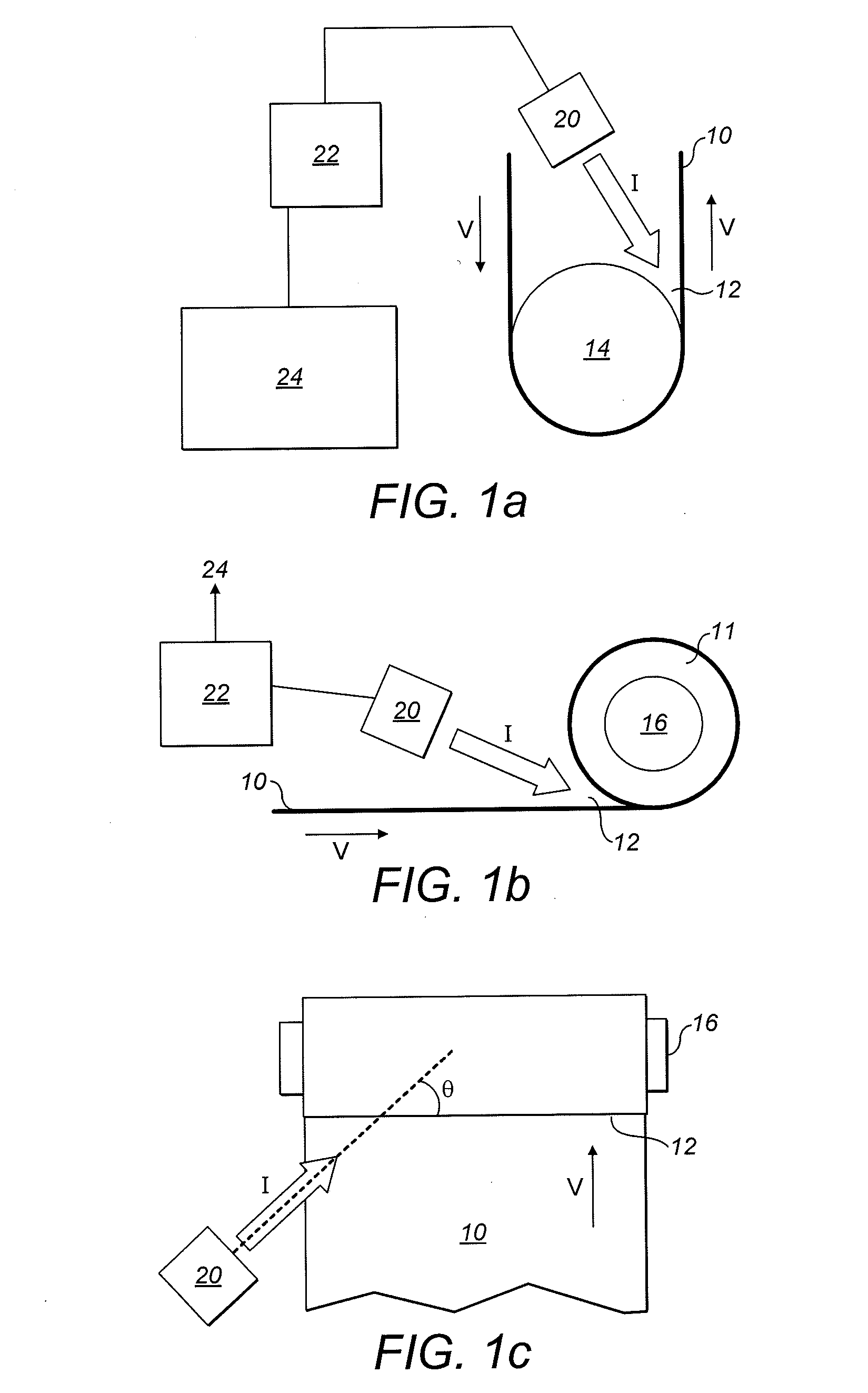
[0092] Suitable apparatus for performing the present invention is shown schematically in FIG. 1. FIG. 1a shows a sheet material 10, such as steel, supported around a roller 14 during a process such as annealing. The sheet material moves as indicated by the arrow v. FIG. 1b gives a second example, in which sheet material 10, such as aluminum strip, is coiled on to a mandrel 16. The mandrel may be split such that it can be expanded during coiling then subsequently collapsed to facilitate removal of the coil 11.

[0093] In both cases a cavity 12 is formed between the sheet material and the roller 14 (or mandrel 16). In FIG. 1a, the sheet material 10 forms only one side of the cavity, whereas in the case of FIG. 1b, both sides are provided by the sheet material, since it is wrapped around mandrel 16. The cavity 12 enhances the effective emissivity of the sheet material to a greater or lesser degree, according to the varying size of the cavity.

[0094] A thermal imaging device 20 is arrang...


PUM

PropertyMeasurementUnit
wavelengthaaaaaaaaaa

Abstract

A method of measuring the temperature of a sheet material arranged such that it forms at least one side of a cavity, so as to enhance the effective emissivity of the sheet material in the vicinity of the cavity comprises: generating a thermal image of at least part of the inside of the cavity, the thermal image comprising a plurality of pixels each having a pixel value representative of radiation emitted by a respective region of the cavity; identifying a first subset of the pixels whose pixel values meet predetermined criteria; using the identified first subset to determine a line on the thermal image representative of optimal emissivity enhancement in the cavity; and selecting a second subset of the pixels based on the determined line and generating a temperature profile along the determined line derived from the pixel values associated with each of the second subset of pixels.

Description

CROSS REFERENCE TO RELATED APPLICATIONS [0001] This application claims priority from British Application No. 0801918.4, filed Feb. 1, 2008, the entire disclosure of which is incorporated by reference. BACKGROUND OF THE INVENTION [0002] This invention relates to methods and apparatus for measuring the temperature of an object, in particular a sheet material, by detecting radiation emitted by the object. [0003] Thermal imagers provide two dimensional temperature images of a scene. Typically, such devices observe and measure infrared emission from the scene, thus providing a measure of temperature without being in contact with the source. Infrared energy is emitted by all materials at temperatures above absolute zero. This energy travels in the form of electromagnetic waves with wavelengths typically in the range 0.7 microns to 20 microns. When an infrared ray is intercepted by a body which is not transparent to the infrared spectrum, it induces electronic transitions or its energy is ...

Claims


Application Information

Patent Timeline
Patent Type & Authority Applications(United States)
IPC IPC(8): G01J5/00G01K3/00G08B17/00
CPCB21B38/006G01J5/0022G01J5/505G01J2005/0085G01J2005/0029G01J2005/0077G01J5/522G01N25/72G01J5/485G01J5/03G01J5/53
Inventor BEYNON, THOMASRIDLEY, IANMETCALFE, STUARTMELLOR, ANDREWWILEMAN, BEN
Owner LAND INSTRUMENTS INTERNATIONAL
Learn More