Motion control device for vehicle

a technology of motion control and vehicle, which is applied in the direction of steering initiation, vessel construction, instruments, etc., can solve the problems of low necessity of preparatory control, and discomfort of the driver

Active Publication Date: 2010-10-21
ADVICS CO LTD
View PDF22 Cites 28 Cited by
  • Summary
  • Abstract
  • Description
  • Claims
  • Application Information

AI Technical Summary

Benefits of technology

[0014]The reference lateral acceleration, which is calculated on the basis of the steering angular velocity, is compared with the actual lateral acceleration of the vehicle, so that a preparatory control is started when the actual lateral acceleration exceeds the ref

Problems solved by technology

Generally, when a preparatory control is executed, a driver may feel discomfort because of a drive noise of an actuator and the like or because of a slight deceleration of the vehicle caused by the preparatory control.
Furthermore, generally, the prep

Method used


Image

  • Motion control device for vehicle
  • Motion control device for vehicle
  • Motion control device for vehicle

Examples


first embodiment

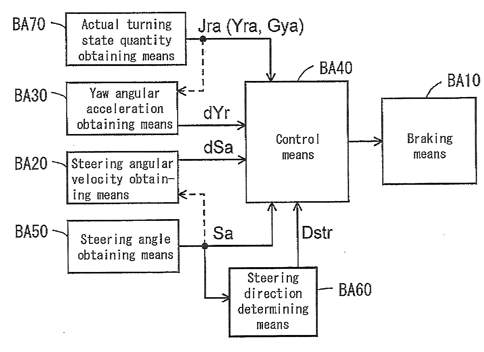
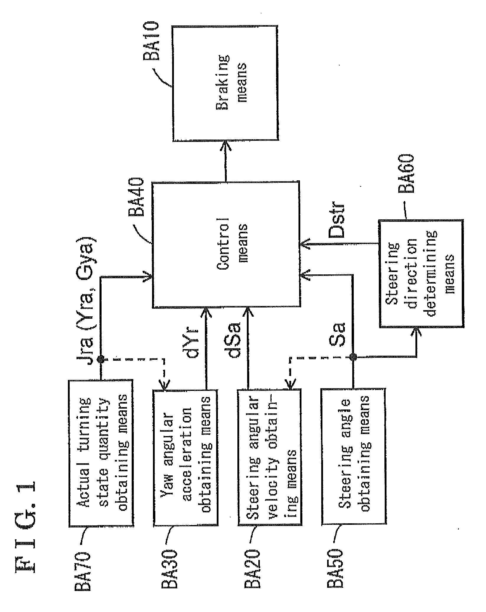
[0043]A first embodiment of a motion control device for a vehicle will be described below with reference to the attached drawings. Illustrated in FIG. 1 is an entire configuration example of the motion control device for the vehicle according to the first embodiment.

[0044]As illustrated in FIG. 1, the motion control device for the vehicle (which will be hereinafter referred to as a device) includes a braking means BA10 for applying a brake torque to a wheel of the vehicle, a steering angular velocity obtaining means BA20 for obtaining a steering angular velocity dSa of the vehicle, a yaw angular acceleration obtaining means BA30 for obtaining a yaw angular acceleration dYr and a control means BA40 for controlling the brake torque to be applied to the wheel via the braking means BA10 on the basis of the steering angular velocity dSa and the yaw angular acceleration dYr. More specifically, the control means BA40 controls the braking means BA10 in order to apply the brake torque to the...

second embodiment

[0122]A second embodiment of a motion control device for a vehicle will be described below with reference to the attached drawings. Illustrated in FIG. 13 is an entire configuration example of the motion control device for the vehicle according to the second embodiment,

[0123]As illustrated in FIG. 13, the motion control device for the vehicle (which will be hereinafter referred to as the device) includes a braking means BB10 for applying the brake torque to the wheel WH**, an actual turning state quantity obtaining means BB20 for obtaining the actual turning state quantity (Yra, Gya and the like) acting on the vehicle, and a first recognizing means BB30 for calculating a first state quantity Jos on the basis of the actual turning state quantity and recognizing the oversteering tendency of the vehicle on the basis of the first state quantity Jos. The device further includes a second recognizing means BB40 for calculating a second state quantity Kos, which differs from the first state...

third embodiment

[0196]A third embodiment of a motion control device for a vehicle will be described below with reference to the attached drawings. Illustrated in FIG. 21 is an entire configuration example of the motion control device for the vehicle according to the third embodiment.

[0197]As illustrated in FIG. 21, the motion control device for the vehicle (which will be hereinafter referred to as the device) includes an actual yaw rate obtaining means BC10 for obtaining the actual yaw rate Yra of the vehicle and a braking means BC20 for applying the brake torque to the wheel WH** of the vehicle. The device maintains the traveling stability of the vehicle by controlling the brake torque, which is applied to the wheel WH**, via the braking means BC20 on the basis of the actual yaw rate Yra. The device further includes a steering angular velocity obtaining means BC30 for obtaining the steering angular velocity dSa of the vehicle, a determining means BC40 for determining a reference lateral accelerati...


PUM


Abstract

A motion control device for a vehicle, including a braking means for applying a brake torque to a wheel of the vehicle and maintaining a traveling stability of the vehicle by controlling the braking means, the motion control device for the vehicle, includes a steering angular velocity obtaining means for obtaining a steering angular velocity of the vehicle, a yaw angular acceleration obtaining means for obtaining a yaw angular acceleration of the vehicle, and a control means for controlling the brake torque on the basis of the steering angular velocity and the yaw angular acceleration.

Description

CROSS REFERENCE TO RELATED APPLICATIONS[0001]This application is based on and claims priority under 35 U.S.C. §119 to Japanese Patent Application 2009-098638, filed on Apr. 15, 2009, Japanese Patent Application 2009-098646, filed on Apr. 15, 2009, and Japanese Patent Application 2009-098653, filed on Apr. 15, 2009, the entire contents of which are incorporated herein by reference.FIELD OF THE INVENTION[0002]The present invention generally relates to a motion control device for a vehicle.BACKGROUND[0003]Disclosed in JP3114647B is a brake system for a behavior control of a vehicle, that “includes a means for detecting a steering angle and a means for detecting a steering angular velocity and that starts actuating a pump means when a degree (a level) of the steering angle becomes equal to or greater than a reference value of the steering angle and when a level of the steering angular velocity becomes equal to or greater than a reference value of the steering angular velocity” in order ...

Claims


Application Information

Patent Timeline
IPC IPC(8): B60T8/1755B62D15/02
CPCB60T2230/02B60T8/17555
Inventor YASUI, YOSHIYUKIKATO, TOSHIHISAYASUTAKE, TOSHIOIKEMATSU, ATSUSHI
Owner ADVICS CO LTD
Why Eureka
Try Eureka