Environment temperature measuring method, liquid sample measuring method, and measuring device

a technology of environment temperature and measuring method, applied in the direction of instruments, heat measurement, calorimeters, etc., can solve the problems of difficult to accurately detect changes in temperature near the sensor, the accuracy of environment temperature measurement suffers, and the rise of the environment temperature inside the measuring devi

Inactive Publication Date: 2010-10-21
PANASONIC HEALTHCARE HLDG CO LTD
View PDF17 Cites 40 Cited by
  • Summary
  • Abstract
  • Description
  • Claims
  • Application Information

AI Technical Summary

Benefits of technology

[0025]Consequently, the internal environment temperature inside the housing of the measuring device and the elapsed time since the start of heat generation from the heat generating material can be measured in real time. This means that the external environment temperature outside the housing can be identified by canceling out the effect of a rise in the internal environment temperature inside the housing caused by heat generation from the heat generating material. Highly accurate temperature correction can then be performed on the measured analysis object concentration on the basis of the external environment temperature information outside the housing thus identified.

Problems solved by technology

Specifically, with the above constitution, the environment temperature inside the measuring device and near the sensor 114 can be measured by the temperature sensor 110 and a temperature detecting system 39, but when a heat generating material having a heat generating action is provided to the measuring device, the environment temperature inside the measuring device rises, which is a problem in that the accuracy of environment temperature measurement suffers.
Also, with the constitution discussed in Patent Citation 2, when the heat generating material is a part mounted on a substrate, it is difficult to accurately detect changes in temperature near the sensor because of heat propagation through the substrate.
Also, a heat seal has to be provided, and since the internal configuration is limited by the heat seal, this hampers efforts to make the device more compact.

Method used


Image

  • Environment temperature measuring method, liquid sample measuring method, and measuring device
  • Environment temperature measuring method, liquid sample measuring method, and measuring device
  • Environment temperature measuring method, liquid sample measuring method, and measuring device

Examples


embodiment 1

[0105]A measuring device 2 pertaining to this embodiment will be described on the basis of FIGS. 1 to 11.

[0106]Here, a blood glucose level measuring device that measures glucose concentration using blood as the analysis object is given and described as an example of the measuring device 2. What is shown in FIGS. 1 to 11 is nothing but an embodiment of the present invention, and the scope of the invention is not limited to or by these drawings.

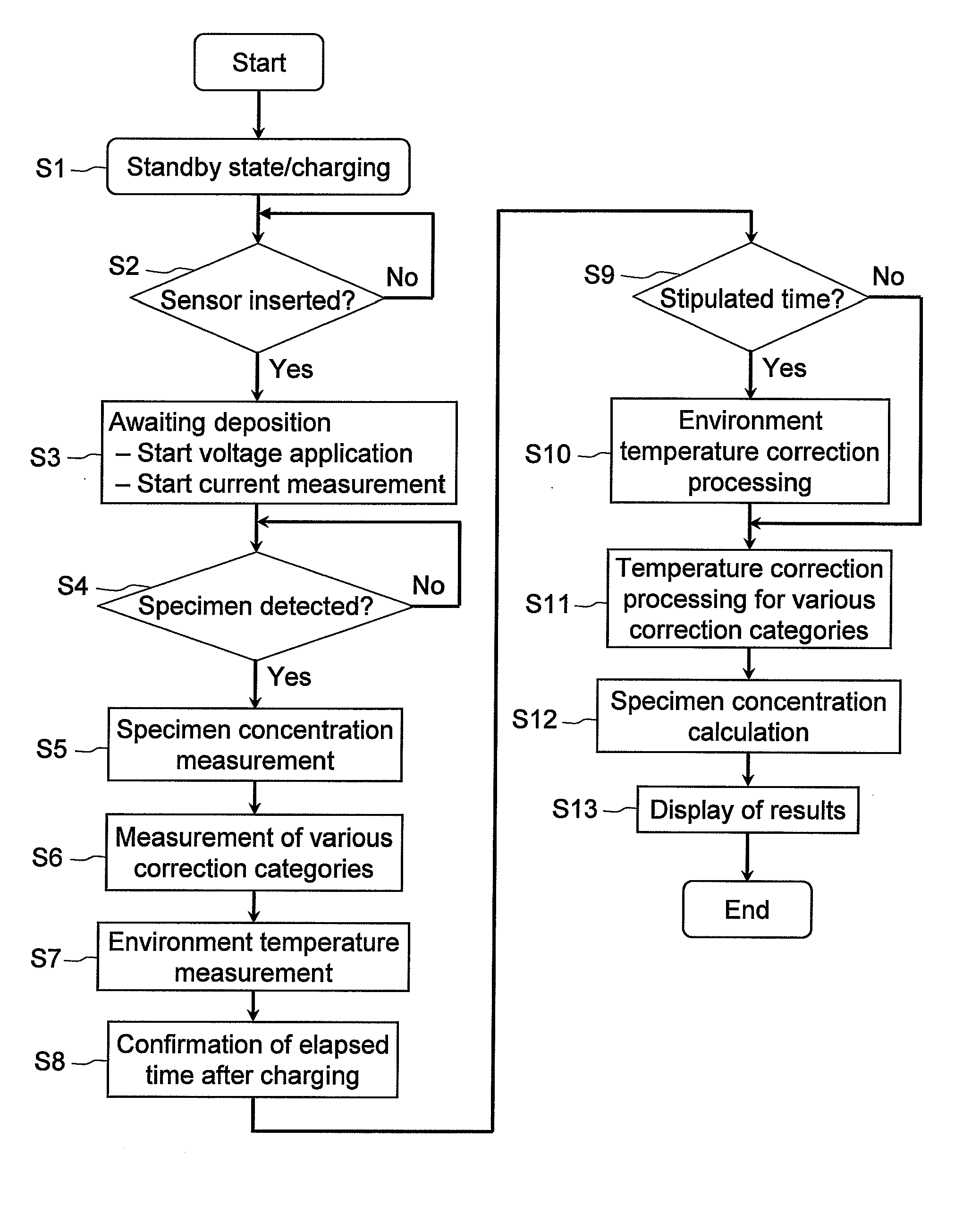
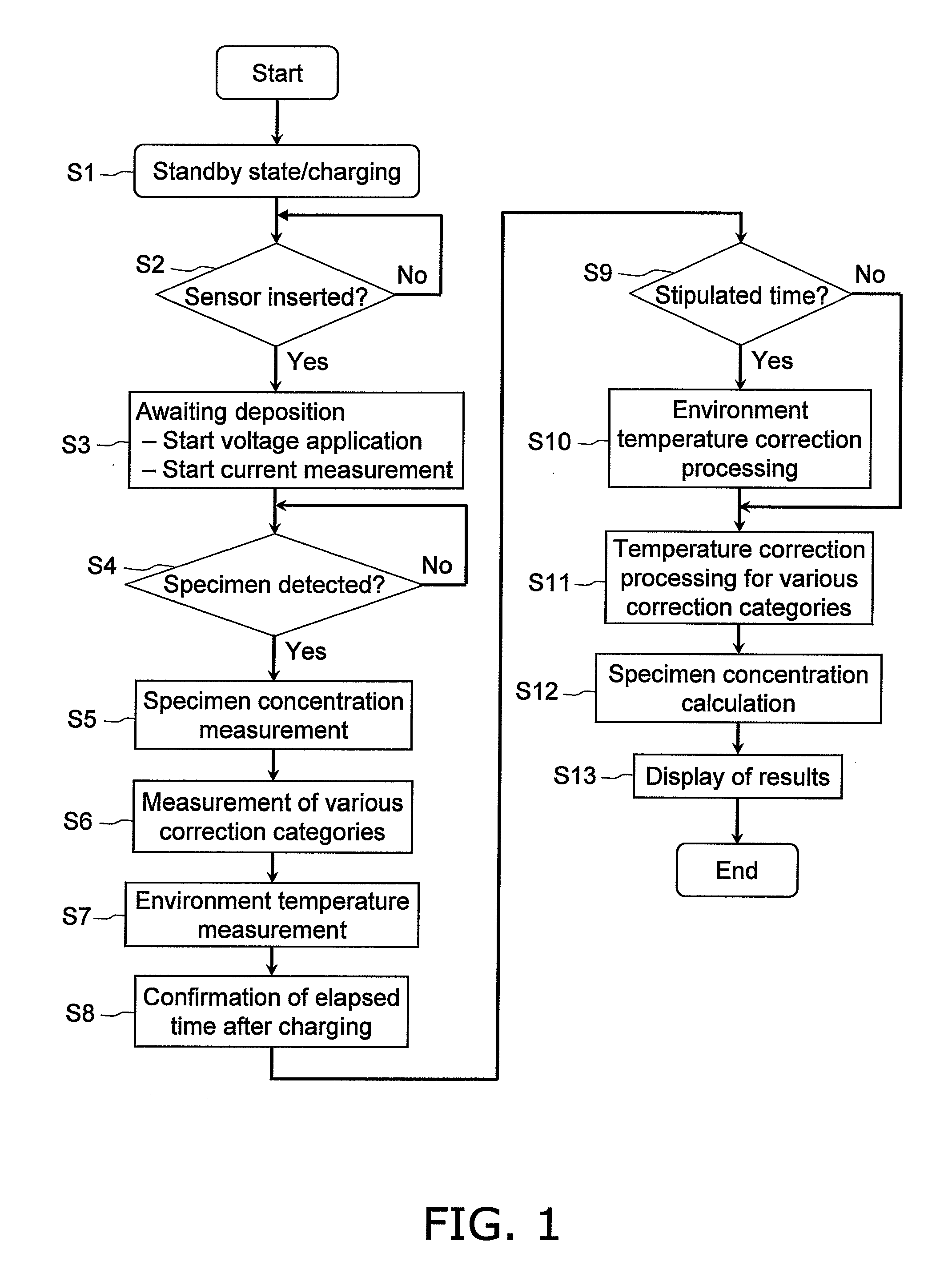
[0107]FIG. 1 is a flowchart showing the overall algorithm when a biosensor 1 pertaining to this embodiment is mounted in the measuring device 2, and then the concentration of the specimen serving as the measurement object is calculated. FIG. 2 is a simplified diagram of the constitution of the measuring device 2 pertaining to this embodiment.

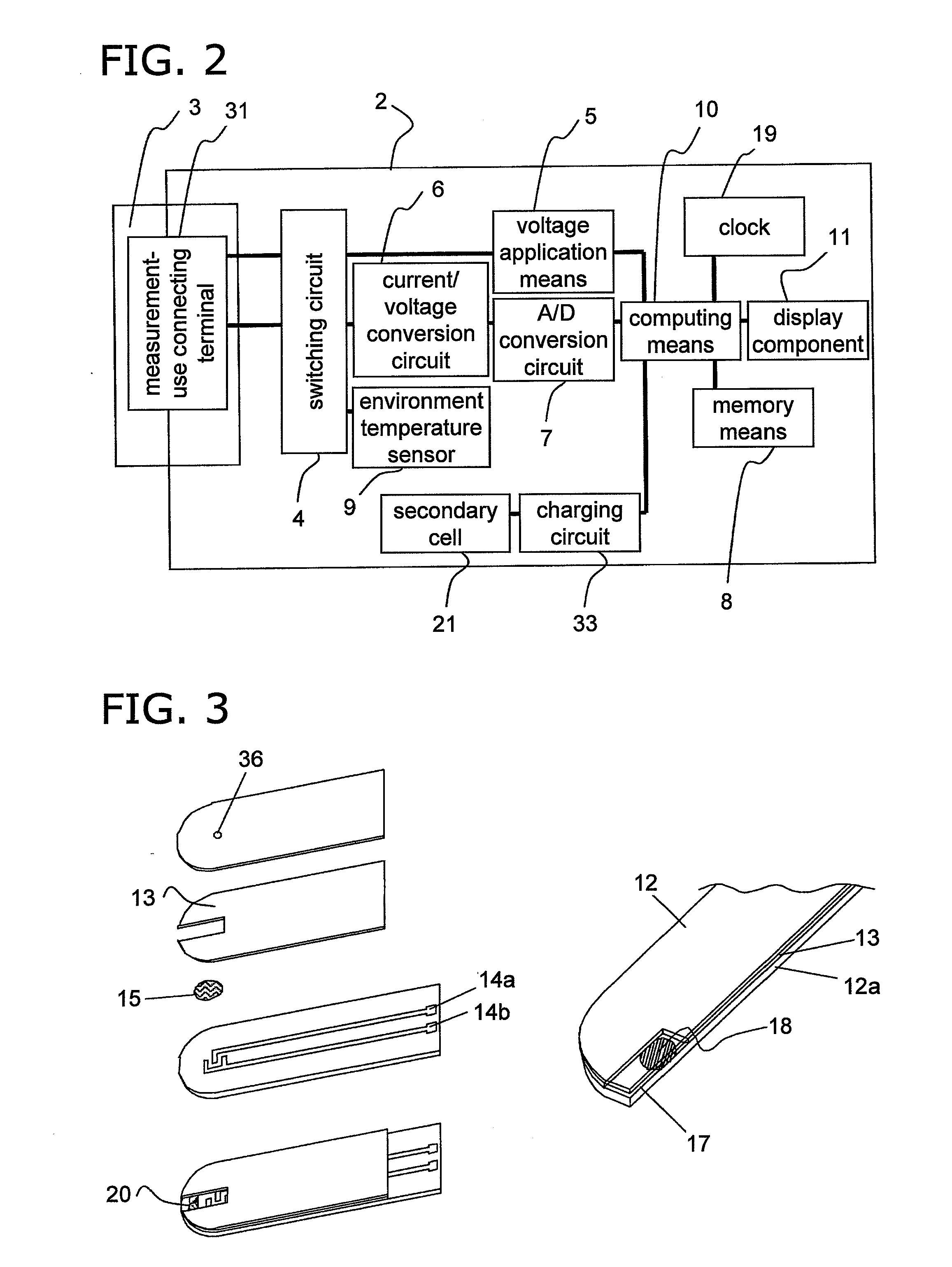
[0108]Next, the biosensor 1, which is a constituent element of the measuring device and method pertaining to this embodiment, will be described in detail. FIG. 3 is an exploded oblique view of the configura...

embodiment 2

[0156]Another embodiment of the present invention will now be described through reference to FIGS. 3, 9, 12, 13, and 14 to 22. The description here, just as in Embodiment 1 above, will be for a blood glucose sensor that measures glucose concentration using blood as the analysis object. What is described below through reference to the drawings is merely an embodiment of the present invention, and the present invention is not limited to or by this.

[0157]FIG. 14 is a flowchart of an overall algorithm for when a specimen concentration is calculated after a biosensor 201 pertaining to this embodiment has been mounted to a measuring device 202. FIG. 15 is a simplified diagram illustrating the measuring device 202 pertaining to this embodiment.

[0158]The biosensor 201, which is a constituent element of the measuring device 202 and method of this embodiment, will be described in detail. An exploded oblique view of the biosensor 201 is the same as FIG. 3 described in Embodiment 1 above, and w...

embodiment 3

[0225]The measuring device pertaining to yet another embodiment of the present invention will now be described through reference to FIG. 26.

[0226]In Embodiments 1 and 2 above, the external environment temperature outside the housing was calculated on the basis of information measured by such as the environment temperature sensor (thermistor) 9 provided to the measuring device 2. However, if the environment temperature sensor 9, etc., should not operate properly for one reason or another, then the external environment temperature cannot be calculated accurately. As a result, the concentration of the specific component in a liquid sample, which has been corrected on the basis of this external environment temperature information, cannot be found accurately, and there is a risk that the measurement accuracy of the measuring device 2 will be poor.

[0227]To solve this problem, in this embodiment the constitution shown in FIG. 26 is employed. Those constituent elements that are in common wi...


PUM

PropertyMeasurementUnit
temperatureaaaaaaaaaa

Abstract

A cavity (17) in which an analysis sample is held and measurement is performed, and an electrode system (14) for measuring the concentration of the sample in the cavity (17) are provided on a biosensor (1). A secondary cell (21) and an environment temperature sensor (9) are provided inside the measuring device (2). The environment temperature during charging is measured in real time by specifying the environment temperature during charging from the time required to charge the secondary cell (21) and the environment temperature during charging. The measured analysis sample concentration is corrected for temperature with high accuracy from the environment temperature information obtained during charging, in a temperature correction step 09, and thus an analysis result with extremely high accuracy is obtained.

Description

TECHNICAL FIELD[0001]The present invention relates to a measuring device for measuring a highly infectious or polluting analysis sample, and more particularly relates to a constitution and measurement method that give high analysis accuracy with a measuring device that makes use of a disposable sensor.BACKGROUND ART[0002]In the field of measuring highly infectious or polluting analysis samples with small devices, and especially with biosensing devices used to protect the health of people, disposable sensors are used in which the part of the sensor that comes into contact with the sample can be removed.[0003]A biosensing device is a device in which the measurement elements of a sensor that recognizes an analysis object include the capability to recognize the molecules of a biological sample, such as microbes, enzymes, or antibodies, and a biological material is used as a molecular labeling element. Specifically, with these biosensing devices, in the course of recognizing a specific c...

Claims


Application Information

Patent Timeline
Patent Type & Authority Applications(United States)
IPC IPC(8): G01K13/00G06F19/00
CPCG01N27/3274G01K7/42G01N27/3272G01N27/3273
Inventor KUSUMOTO, KUNIMASA
Owner PANASONIC HEALTHCARE HLDG CO LTD
Why Eureka
Try Eureka