Method and device for defining a beam of high-energy rays

Active Publication Date: 2010-10-28
DEUTES KREBSFORSCHUNGSZENT STIFTUNG DES OFFENTLICHEN RECHTS
View PDF5 Cites 10 Cited by
  • Summary
  • Abstract
  • Description
  • Claims
  • Application Information

AI Technical Summary

Benefits of technology

[0032]The basic concept of the invention is that an adjustable iris diaphragm can be brought more quickly to the required size than is possible by the changing of solid diaphragms. In contrast, relative to diaphragm leaves with several openings that can be brought into the beam path, it has both less weight and also greater flexibility with regard to the adjustable diaphragm opening width.
[0033]The construction is relatively simple and the posi

Problems solved by technology

These excessively irradiated areas were generated since the contour of the ill tissue was not simulated by the collimators and also since half shadows were generated at the boundaries of the irradiated area, where, in particular with large irradiation fields, the entire strength of the shielding material was not available, since it was not oriented parallel to the rays.
Since tumors tend to have a round rather than square shape, there are large excessively irradiated corner areas.
This collimator, however, does not sufficiently simulate the tumor shape and provides no suppression of half shadows.
The problem of simulation of the shape of a tumor or another area to be irradiated is, however, only very insufficiently solved, and the problem of half shadows is not solved at all.
However, this collimator only forms square irradiation fields, such that large excessively irradiated areas on the corners must be accepted.
A further disadvantage of this approach consists in that only polygons can be formed as irradiation field limitation in dependence on the number of plates, and shaping of the true tumor contour is not possible.
This device only permits very limited point irradiation.
Moreover, the effect of reflection on reflecting inner surfaces is not suited for therapeutic rays which are in a megavolt range.
The disadvantage is, however, that the method is complicated, requiring permanent collimator change, which consumes a great deal of time on expensive devices, and is also costly since many collimators must be produced for each irradiation, which are useless after that, since they are determined for use for one patient only and can be used for that patient only within a limited time period, since the shape of the tumor permanently changes due to growth, decrease, or shape changes.
These multileaf collimators were initially advantageous in that almost any shape could be quickly adjusted, but are disadvantageous in that the mecha

Method used


Image

  • Method and device for defining a beam of high-energy rays
  • Method and device for defining a beam of high-energy rays
  • Method and device for defining a beam of high-energy rays

Examples


Example

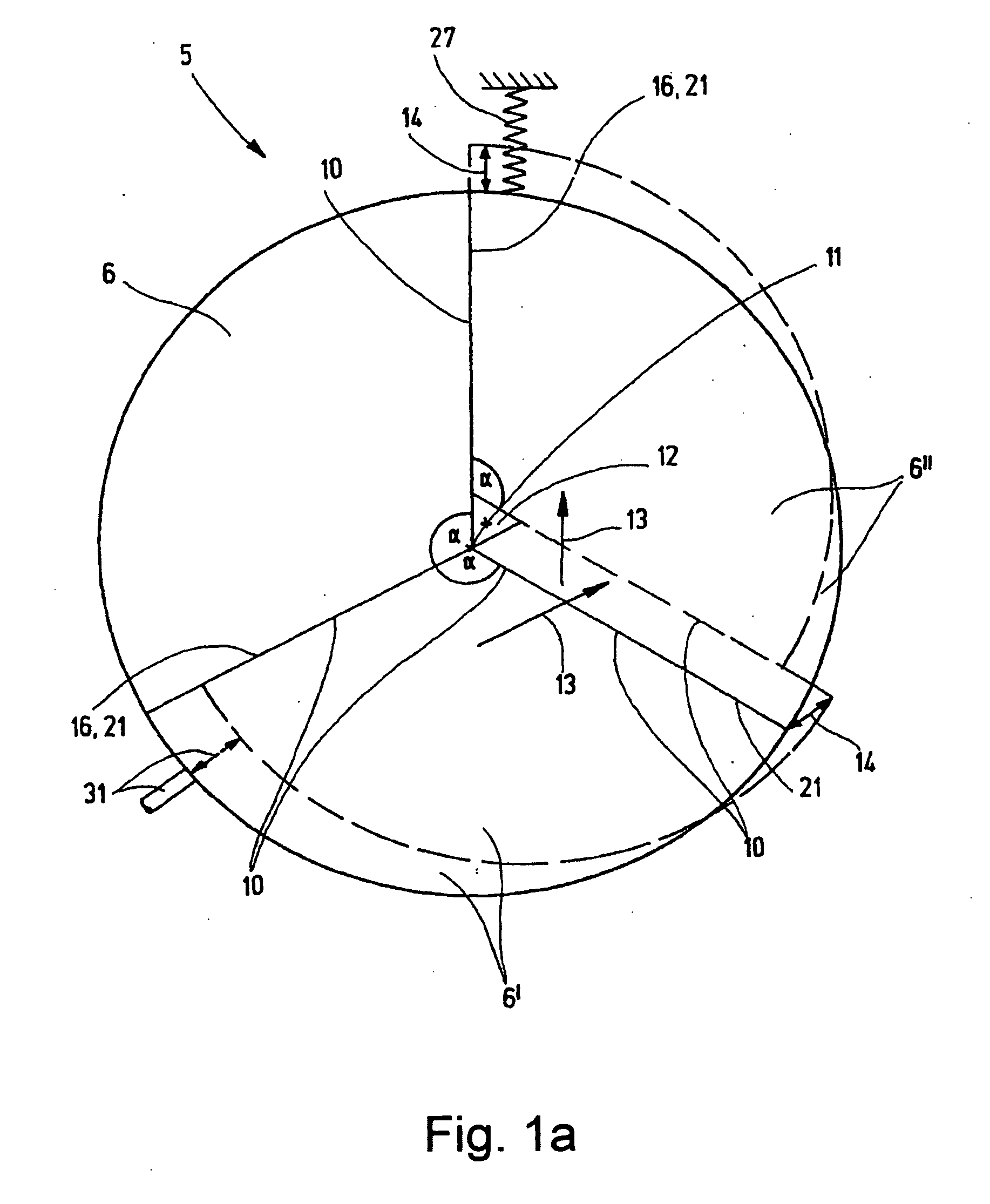
[0070]FIG. 1a shows a simple embodiment of a three-leaf iris diaphragm 5 for explaining the principle. A three-leaf iris diaphragm 5 was selected for this explanation because it can be most clearly illustrated due to the small number of parts. This iris diaphragm 5 is provided with three diaphragm leaves 6, 6′, and 6″. For this embodiment, the diaphragm leaf 6 is fixed and the diaphragm leaves 6′ and 6″ can move in the direction of the arrow 13. In the closed state of the iris diaphragm 5, the angles α are located at the center 11, wherein each angle α is formed by two side surfaces 10 of the diaphragm sheets 6, 6′, 6″. These angles α naturally become correspondingly smaller for iris diaphragms 5 with more diaphragm leaves.

[0071]In this embodiment, the diaphragm leaves 6′ and 6″ are guided by means of guides 21 on the side surfaces 10, such that the side surfaces 10 contact each other tightly. In this way, due to the fixed arrangement of the diaphragm leaf 6, its side edges 10 form ...


PUM


Abstract

The invention relates to a method and device for operating collimator (1) for limiting a beam of high-energy radiation (2) which, starting from an essentially point-shaped radiation source (3), is directed onto an object (4) to be treated and which is used especially for stereotactic, conformal radiation therapy of tumors, wherein the collimator (1) has an iris diaphragm (5) as a beam-limiting means. For such a collimator (1), a high degree of shielding for minimal overall height and with a variable opening size of the diaphragm opening (12) is achieved, in that the iris diaphragm (5) has at least three diaphragm leaves (6, 6′, 6″, or 7, 7′, 7″, 7′″, or 8, 8′, 8″, 8′″, 8″″, or 9, 9′, 9″, 9′″, 9″″, 9′″″) which have touching side surfaces (10) enclosing the same angle (α), wherein the diaphragm leaves (6, 6′, 6″, or 7, 7′, 7″, 7′″, or 8, 8′, 8″, 8′″, 8″″, or 9, 9′, 9″, 9′″, 9″″, 9′″″) open up a beam-limiting opening (12) such that a sliding movement (13) along the side surfaces (10) takes place by a number of diaphragm leaves (6, 6′, 6″, or 7, 7′, 7″, 7′″, or 8, 8′, 8″, 8′″, 8″″, or 9, 9′, 9″, 9′″, 9″″, 9′″″) which is reduced by at most one.

Description

[0001]This application is a continuation in part of Ser. No. 11 / 919,707 filed on Oct. 31, 2007 as a 371 of PCT / EP2005 / 008659 filed Aug. 10, 2005 and claiming Paris Convention priority to EP 05009871.4 filed May 6, 2005 the entire disclosures of which are hereby incorporated by referenceBACKGROUND OF THE INVENTION[0002]The invention relates to a method and device having a collimator for limiting a beam of high-energy radiation directed from an essentially point-shaped radiation source onto an object to be treated for stereotactic, conformal radiation therapy of tumors, wherein the collimator has a scanning device with a collimator and a drive mechanism for scanning an area of an object being treated with a beam of rays defined by the collimator.[0003]Collimators for limiting a beam of high-energy radiation are used for diagnostic purposes and for the treatment, in particular, of tumors. Here, the collimators are used to limit the beam, so that healthy tissue lying next to the diagnos...

Claims


Application Information

Patent Timeline
IPC IPC(8): A61N5/00
CPCA61N5/1042A61N5/1036
Inventor ECHNER, GERNOT
Owner DEUTES KREBSFORSCHUNGSZENT STIFTUNG DES OFFENTLICHEN RECHTS
Why Eureka
Try Eureka