This helps you quickly interpret patents by identifying the three key elements:
Problems solved by technology
Method used
Benefits of technology
Benefits of technology
[0007]In view of the foregoing disadvantages, it is an object of the invention to provide the top board structure of office furniture in which a reinforcing frame can be assembled and welded more easily, the top board structure providing less weight but sufficient strength, abnormal noise being reduced even if impact is given.
Problems solved by technology
Flexibility in design is not good and its appearance becomes poor.
But if impact is given, abnormal noise is likely to occur.
It is very difficult to join an upper plate on a lower plate.
Its manufacturing is complicated to increase cost.
Method used
Image
Click on the blue label to locate the original text in one second.
Reading with bidirectional positioning of images and text.
Examples
first embodiment
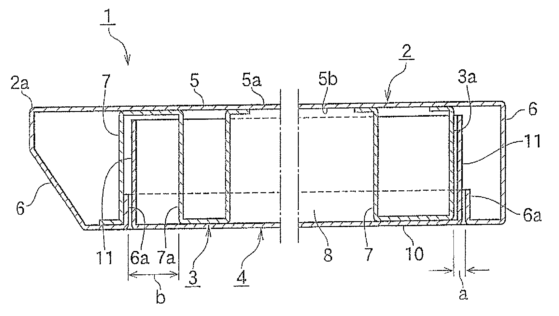
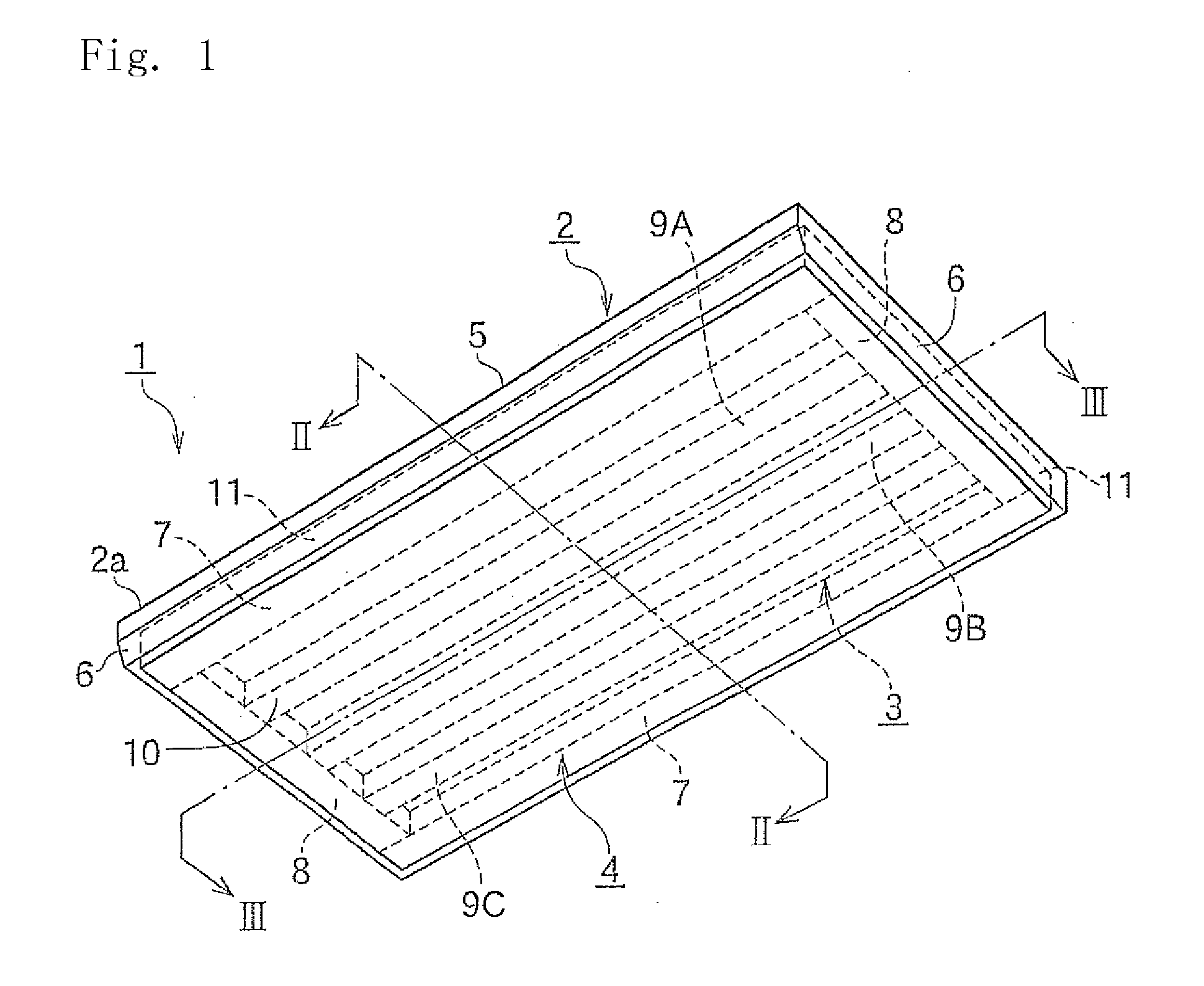
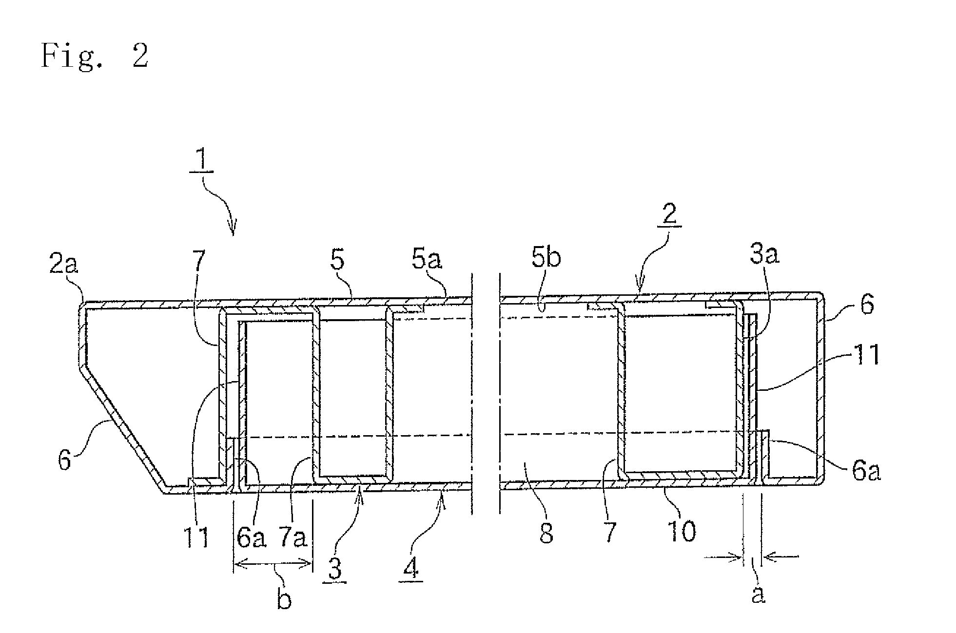
[0020]FIG. 1 is an enlarged perspective view of a top board according to the present invention, seen from below; FIG. 2 is a vertical sectional view taken along the line II-II in FIG. 1; FIG. 3 is a verticals sectional view taken along the line and FIG. 4 is an exploded perspective view showing how to mount a reinforcing frame and a bottom cover to the top board upside down.
[0021]In FIG. 1, a top board 1 comprises a top board body 2 on which a computer is placed; a reinforcing frame 3; and a bottom cover 4 made of the same material such as sheet metal.
[0022]In FIGS. 2 and 3, the top board body 2 comprises a base 5 the upper surface 5a of which is used for working; and a downward portion 6 which extends downward from the outer periphery of the base 5. At the front edge 2a of the top board body 2, the downward portion 6 is tilted rearward.
[0023]In FIG. 4, the reinforcing frame 3 comprises a longitudinal reinforcement 7 extending along the periphery in a right and left direction; and a...
second embodiment
[0035]FIG. 5 is a partially enlarged perspective view of a top board according to the present invention seen from below; FIG. 6 is an enlarged sectional view taken and seen along the line VI-VI in FIG. 5; FIG. 7 is an exploded perspective view of a reinforcing frame and a bottom cover mounted to the top board in FIG. 5 upside down; and FIG. 8 is an exploded perspective view of the reinforcing frame.
[0036]In FIG. 5, the top board 12 in this embodiment comprises a top board body 13, a reinforcing frame 14 and a bottom cover 15.
[0037]In FIGS. 6 and 7, the top board body 13 has a downward portion 17 extending downward from the periphery of a base 16. The lower end of the downward portion 17 is bent inward like L to form a standing portion 17a, so that the top board body 13 is formed like a box having a lower opening.
[0038]The reinforcing frame 14 comprises a plurality of lateral reinforcements 18 extending in a forward and rearward direction; and a plurality of longitudinal reinforcemen...
fourth embodiment
[0067]FIG. 11 is an exploded perspective view showing a reinforcing frame in the present invention.
[0068]In FIG. 11, the reinforcing frame 39 has the same cross section as those of the lateral and longitudinal reinforcements 18,19 in the second embodiment. In the middle of the lower horizontal portion 40a of a lateral reinforcement 40, there is formed a cutaway portion 42 that engages with the lower horizontal portion 41a of a longitudinal reinforcement 41.
[0069]In the middle of the longitudinal reinforcement 41, there is formed an L-sectioned cutaway portion 43 extending from the lower horizontal portion 41a to the upper horizontal portion 41c through the vertical portion 41b.
[0070]The cutaway portion 43 is engaged with the upper horizontal portion 40a of the lateral reinforcement 40 though the vertical portion 40c.
[0071]The upper horizontal portion 41c of the longitudinal reinforcement 41 contacts the upper horizontal portion 40b of the lateral reinforcement 30 to allow the rein...
PUM
Abstract
A top board structure capable of easily and simply assembling and welding a reinforcing frame to a top board body, providing a sufficient strength with a reduced weight, and reducing abnormal noise that might occur when an impact is applied. A reinforcing frame formed by assembling lateral reinforcing member directed in a lateral direction with a longitudinal reinforcing member directed in a longitudinal direction is fixed to the lower surface of a base board in a top board body formed at the peripheral edge thereof in a box shape opened downward by a downward piece, a rear surface cover in a box shape opened upward by an upward piece is formed at the peripheral edge of a cover base board, and the rear surface cover is fixed to the top board body with the upward piece of the rear surface cover kept fitted / inserted into gaps formed between the inside surface of the erect piece portion of the downward piece in the top board body and the outside portion of the reinforcing frame or the inside partition wall of the reinforcing member constituting the reinforcing frame.
Description
BACKGROUND OF THE INVENTION[0001]The present invention relates to the top board structure of office furniture such as a table and a desk used in an office.[0002]The top board of a table or a desk is made of wood or a wooden base on which a decoration plate such as melamine resin is applied. To keep sufficient strength, it is necessary to thicken the base. Flexibility in design is not good and its appearance becomes poor. The top board also becomes heavier. It is necessary to strengthen the support structure for the top board.[0003]JP2003-174935A discloses that the top board of a table is made of resin on which Al is applied, but is not preferable in view of environmental aspects such as wastes and recycling.[0004]The top board of a table is made of sheet metal. But if impact is given, abnormal noise is likely to occur. In order to keep sufficient strength, it is necessary to increase thickness of the sheet metal.[0005]The top board becomes heavier as well as wooden base. JP2005-1377...
Claims
Application Information
Patent Timeline
Application Date:The date an application was filed.
Publication Date:The date a patent or application was officially published.
First Publication Date:The earliest publication date of a patent with the same application number.
Issue Date:Publication date of the patent grant document.
PCT Entry Date:The Entry date of PCT National Phase.
Estimated Expiry Date:The statutory expiry date of a patent right according to the Patent Law, and it is the longest term of protection that the patent right can achieve without the termination of the patent right due to other reasons(Term extension factor has been taken into account ).
Invalid Date:Actual expiry date is based on effective date or publication date of legal transaction data of invalid patent.

