Compact multi membrane vessel for water ultrafiltration

Inactive Publication Date: 2016-04-07
SIEMENS AG
View PDF0 Cites 0 Cited by
  • Summary
  • Abstract
  • Description
  • Claims
  • Application Information

AI Technical Summary

Benefits of technology

[0009]It may be an objective of the present invention to provide a filtration vessel which comprises a compact design

Problems solved by technology

This may lead to a large footprint

Method used


Image

  • Compact multi membrane vessel for water ultrafiltration
  • Compact multi membrane vessel for water ultrafiltration
  • Compact multi membrane vessel for water ultrafiltration

Examples


Example

[0051]The illustrations in the drawings are schematical. It is noted that in different figures, similar or identical elements are provided with the same reference signs.

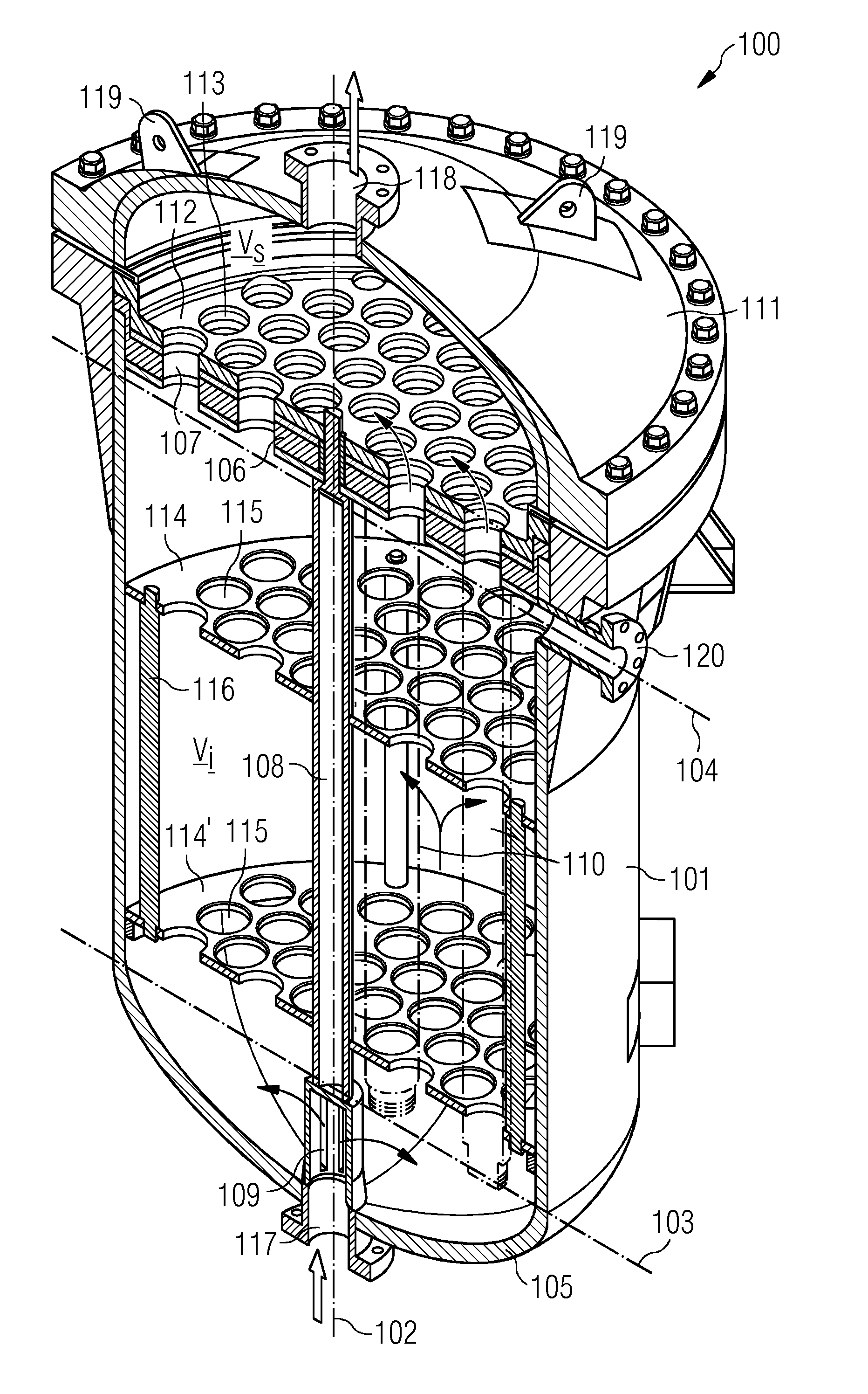
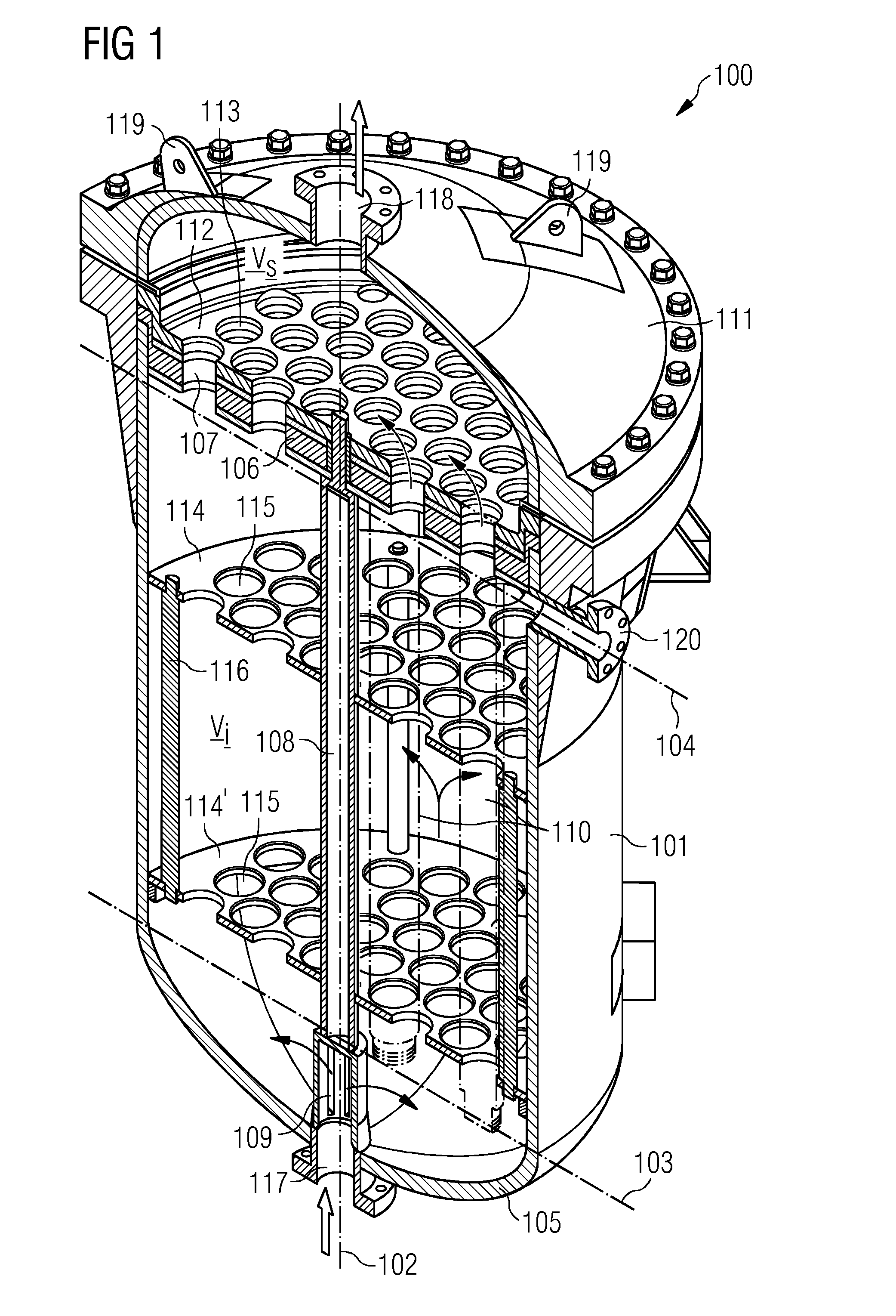
[0052]FIG. 1 shows a filtration vessel 100 for at least partially removing a contaminant from a fluid (e.g. wastewater). The filtration vessel 100 comprises a vessel body 101, a first end cap 105, a supporting plate 106, an inlet pipe 108 and at least one membrane rod 110.

[0053]The vessel body 101 comprises a tubular, cylindrical section extending along a centre axis 102 of the vessel body 101. The centre axis 102 defines an axial direction. The vessel body 101 comprises a first axial end 103 and a second axial end 104. The second axial end 104 is located opposite with respect to the first axial end 103 along the axial direction 102. The first end cap is mounted to the first axial end 103. The first end cap 105 may be integrally formed with the vessel body 101 or may be detachably coupled to the vessel body 101.

[0054...


PUM


Abstract

A filtration vessel at least partially removes a contaminant from a fluid. The vessel has an inlet pipe which is mounted to a first end cab and to a supporting plate of the vessel. The inlet pipe has at least one slot through which the fluid is injectable into an inner volume of a vessel body. At least one membrane rod including a plurality of membrane straws is mounted to the first through hole of the supporting plate such that the membrane rod extends from the supporting plate into the inner volume. A method for backwashing the device includes injecting gas in the storage volume and a method of detection of leaks uses gas bubbles.

Description

CROSS REFERENCE TO RELATED APPLICATIONS[0001]This application is the US National Stage of International Application No. PCT / EP2014 / 053675 filed Feb. 26, 2014, and claims the benefit thereof. The International Application claims the benefit of European Application No. EP13166797 filed May 7, 2013. All of the applications are incorporated by reference herein in their entirety.FIELD OF INVENTION[0002]The present invention relates to a filtration vessel, in particular an ultrafiltration vessel, and to a method for operating the filtration vessel. Furthermore, the present invention relates to a method for cleaning a membrane element, such as a membrane rod comprising approximately 6100 to 6700 membrane straws, within the filtration vessel and to a method for detecting a defect membrane rod within a filtration vessel.[0003]ART BACKGROUND[0004]Ultrafiltration is employed to separate or remove particles larger than sizes of about e.g. 0.01 to 0.1 μm, depending upon the pore sizes of the ult...

Claims


Application Information

Patent Timeline
IPC IPC(8): B01D63/06G01M3/06B01D65/10C02F1/44B01D61/14B01D65/02
CPCB01D63/06B01D61/145B01D65/02B01D65/102B01D2313/025G01M3/06C02F2303/16B01D2321/04C02F1/444B01D63/043B01D65/104B01D2313/06B01D2313/10B01D2313/56
Inventor DIAZ MESA, ARMANDODRIVARBEKK, KRISTIN HELEN BLUMEFLOBERG, ERIKMEHLEN, MARI
Owner SIEMENS AG
Why Eureka
Try Eureka