Lens with controlled light refraction

a technology of controlled light refraction and light output, which is applied in the direction of optics, condensers, instruments, etc., can solve the problems of less than fully efficient illumination patterns, led-emitted light is often lost, and the light output of the lens is often short of the most highly desirable performance, so as to improve the control of the direction of light exiting the optics and improve the light output efficiency.

Active Publication Date: 2010-10-28
IDEAL IND LIGHTING LLC
View PDF54 Cites 49 Cited by
  • Summary
  • Abstract
  • Description
  • Claims
  • Application Information

AI Technical Summary

Benefits of technology

[0008]Another object of the invention is to provide an LED lens with improved light-output efficiency.
[0009]Another object of the invention is to provide an LED lens with improved control of the direction of light exiting the optic.
[0011]This invention is a lens with improved efficiency of output of light from a light emitter which has an emitter axis and defines an emitter plane. It is preferred that the light emitter is an LED package which is free of a surrounding reflective surface. Such improved efficiency of light output from a light emitter is achieved with the inventive lens positioned over the emitter and specifically designed for controlled refraction of light at a lens output surface. The inventive lens provides useful output of almost all of the emitted light, including light emitted at angles which previously resulted in the loss of such light.

Problems solved by technology

However, such lenses have tended to fall short of the most highly desirable performance in that some of the LED-emitted light is often lost.
Typically, some of the LED-emitted light rays are oriented at angles that previously would result in illumination of undesirable areas and thus produce less than fully efficient illumination patterns.
Even though these steps were deemed necessary to achieve desired illumination patterns and to prevent so-called lighting “trespass,” they resulted in lost light and decreased efficiency of LED illuminators.
This has made it very difficult to control refraction of such light.
As a result, only a portion of light being refracted is refracted in a desired direction, while the reminded exited the lens with very little control.

Method used


Image

  • Lens with controlled light refraction
  • Lens with controlled light refraction
  • Lens with controlled light refraction

Examples


Embodiment Construction

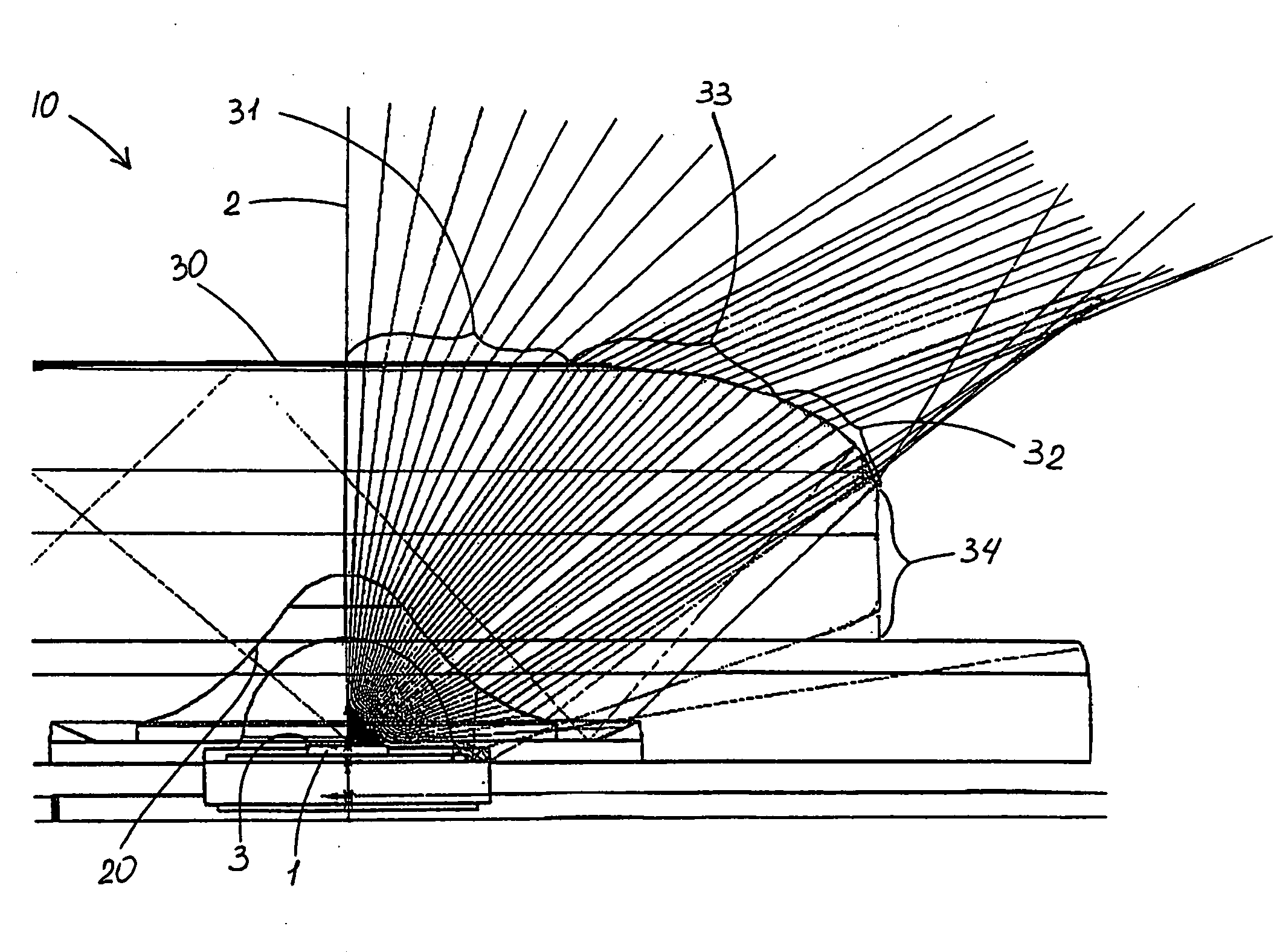
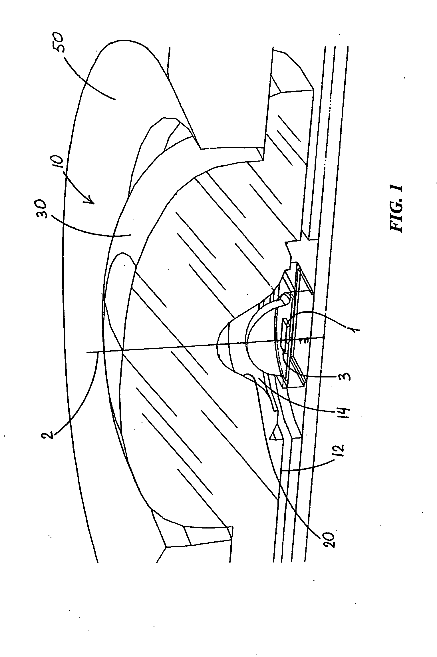
[0027]FIGS. 1-7 illustrate lens 10 which is a preferred embodiment of the invention. Lens 10 is for directing light from a light emitter 1 which has an emitter axis 2 and defines an emitter plane 3. Lens 10 includes an emitter-adjacent base end 12 forming an opening to an inner cavity 14 surrounding emitter 1. Cavity 14 defines a space between emitter 1 and an inner-cavity surface 20 such that emitter light goes through air to enter lens material at inner-cavity surface 20. Because air and the lens material, which may be acrylic or other suitable material, have different refraction indexes resulting in bending of the light at inner-cavity surface 20.

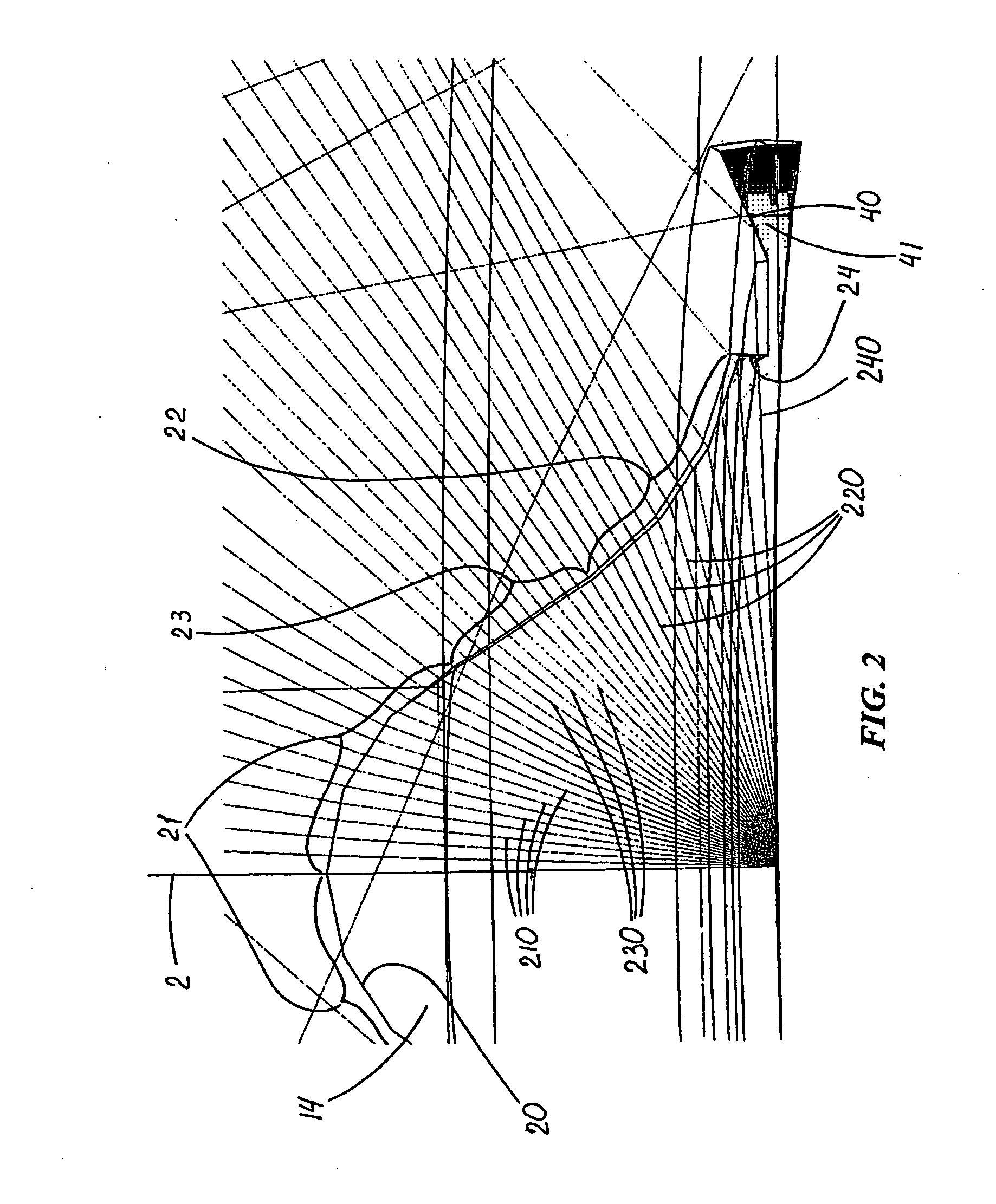
[0028]FIG. 2 best shows configuration of inner-cavity surface 20 which includes an axis-adjacent first inner region 21, a second inner region 22 spaced from first inner region 21, and a middle inner region 23 which joins first and second regions 21 and 22 and is substantially asymptotical to first and second inner regions 21 and 22.

[0029...


PUM


Abstract

A lens for distribution of light from a light emitter having an emitter axis and defining an emitter plane. The lens including an emitter-adjacent base end forming an opening to an inner cavity surrounding the emitter. An inner-cavity surface includes an axis-adjacent first inner region configured for refracting emitter light rays away from the axis, a second inner region spaced from the first inner region and configured for refracting emitter light rays toward the axis, and a middle inner region joining and substantially cross-sectionally asymptotical to the first and second inner regions. The middle inner region is positioned with respect to the emitter to refract light away from the axis by progressively lesser amounts at positions progressively closer to the second inner region. The lens further has an outer surface including output regions each configured for refracting the light from a corresponding one of the inner regions such that at the outer surface light from each inner region is refracted substantially without overlapping light from the other inner regions.

Description

FIELD OF THE INVENTION[0001]This invention relates to lighting fixtures and, more particularly, to optics designed for desired LED light distribution. This invention also relates to the field of LED optics.BACKGROUND OF THE INVENTION[0002]In recent years, the use of light-emitting diodes (LEDs) for various common lighting purposes has increased, and this trend has accelerated as advances have been made in LEDs and in LED-array bearing devices, often referred to as “LED modules.” Indeed, lighting needs which have primarily been served by fixtures using high-intensity discharge (HID) lamps, halogen lamps, compact florescent light (CFL) and other light sources are now increasingly beginning to be served by LEDs. Creative work continues in the field of LED development, and also in the field of effectively utilizing as much of the light emitted from LEDs as possible.[0003]Some efforts have been made to develop small lenses for directing light emitted by small LED packages, and utilizing ...

Claims


Application Information

Patent Timeline
Patent Type & Authority Applications(United States)
IPC IPC(8): G02B3/04G02B3/10
CPCG02B27/0966G02B17/0856G02B3/00G02B3/04G02B19/0061G02B2003/0093
Inventor WILCOX, KURT S.
Owner IDEAL IND LIGHTING LLC
Why Eureka
Try Eureka