Apparatus and a method for detecting a communication channel

a communication channel and apparatus technology, applied in the direction of electrical apparatus, wireless communication services, wireless commuication services, etc., can solve the problems of reduced data transmission rate for users concerned, increased bit error rates, limited permissible transmission signal power, etc., and achieve the effect of maximising the data transmission rate of different terminal devices inside the aircraft cabin

Active Publication Date: 2010-10-28
AIRBUS OPERATIONS GMBH
View PDF4 Cites 23 Cited by
  • Summary
  • Abstract
  • Description
  • Claims
  • Application Information

AI Technical Summary

Benefits of technology

[0009]The detection apparatus according to the invention detects in a frequency band Δf radio signals which are transmitted simultaneously by different radio signal sources. If one of the radio signal sources is a radio signal source of a crew member or of the wireless on-board radio system, the latter always has priority. The configuration logic allocates to the remaining radio signal sources other frequency bands Δf, preferably in the same frequency range ΔF. This ensures that a crew member is not disturbed, during his/her information transmission, by another radio signal source inside the aircraft cabin, e.g. a transmitter of a mobile terminal device. If the apparatus device according to the invention detects that different radio signal sources are using one frequency band Δf simultaneously, and that none of the radio signal sources belongs to the wireless on-board radio system, it may

Problems solved by technology

Unlicensed frequency bands are available to all users for signal transmission, but the permissible transmission signal power is limited.
Consequently the data transmission rate for the users concerned is reduced and this may result in increased bit error rates due to interference.
Another disadvantage of a conventional communication system for transmitting data inside an aircraft cabin of an aircraft lies in the fact that previously a separate on-board communication system had to be provided to guarantee, in any situat

Method used


Image

  • Apparatus and a method for detecting a communication channel
  • Apparatus and a method for detecting a communication channel
  • Apparatus and a method for detecting a communication channel

Examples


Embodiment Construction

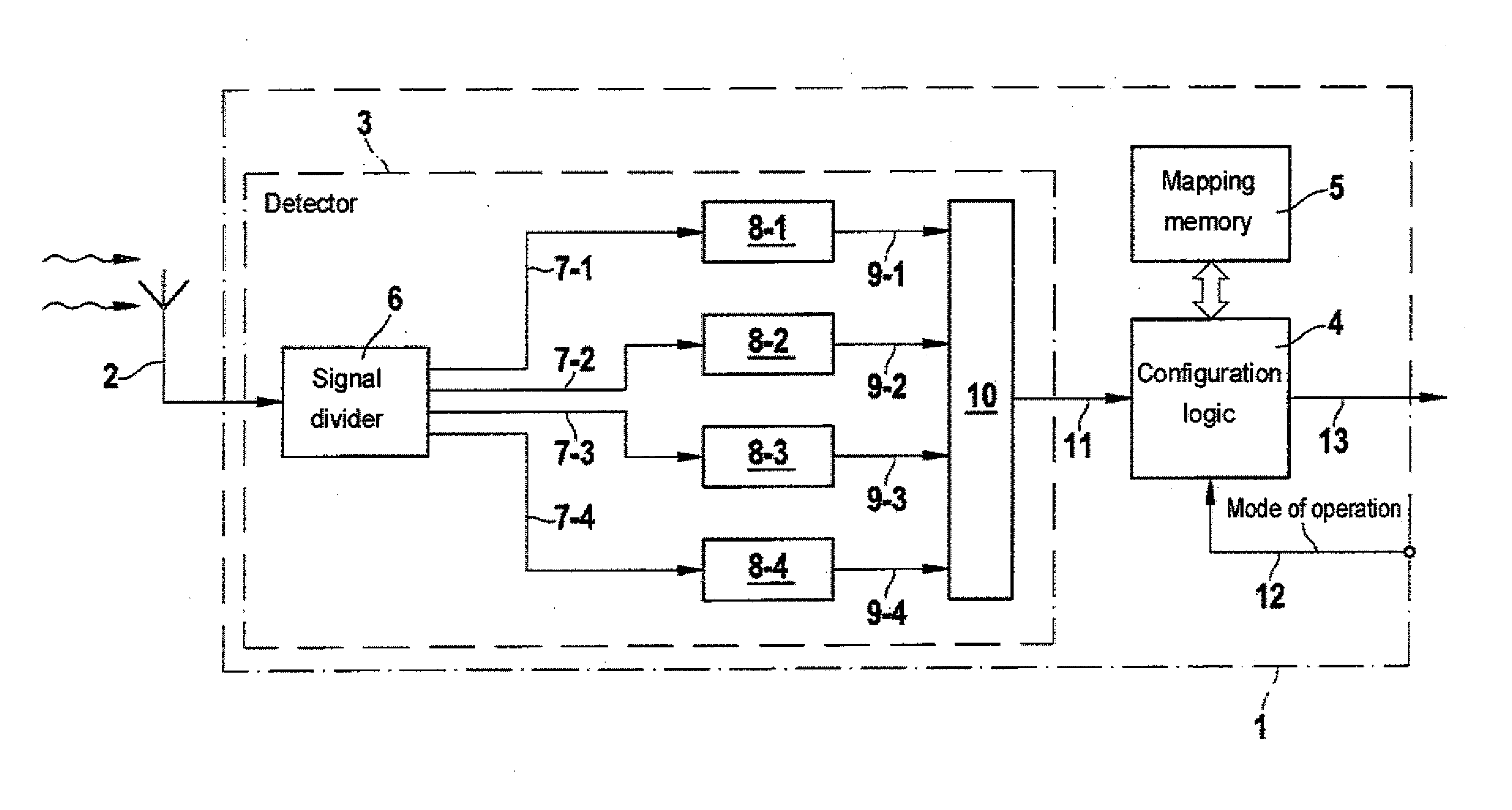
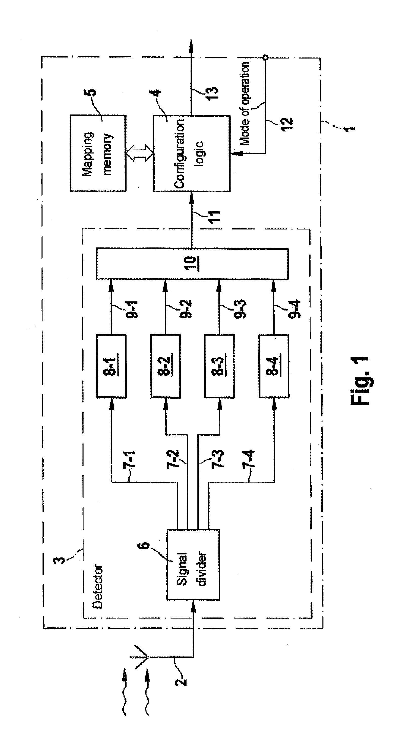
[0017]As can be seen from FIG. 1, the detection apparatus 1 for detecting a communication channel in whose frequency band (A f) radio signals are transmitted from different radio signal sources inside a cabin has a wide band antenna 2, a detector 3 and a configuration logic 4 which, in the exemplary embodiment shown in FIG. 1, is connected to a memory 5. Wide band antenna 2 serves to receive the radio signals transmitted inside the aircraft cabin. Wide band antenna 2 is connected to a signal divider 6 which divides the signal received signal divider 6 may, for example, be a single signal node which distributes the signal received. Alternatively, signal divider 6 may also be formed by a demultiplexer which switches the received signal successively to different outputs.

[0018]Signal divider 6 is connected by cables 7-i to different demodulators 8-i. In the exemplary embodiment shown in FIG. 1 detector 3 contains four different demodulators 8-1 to 8-4. Each demodulator 8-i demodulates t...


PUM


Abstract

The present invention provides a method and an apparatus for detecting a communication channel in whose frequency band radio signals are transmitted by different radio signal sources inside a cabin. In this case a wide band antenna receives the radio signals transmitted inside the cabin. Different demodulators are provided, each of which demodulate the radio signals received by the wide band antenna within an associated frequency range of the demodulator. A configuration logic establishes whether, in a frequency hand within a demodulated frequency range, radio signals are being transmitted simultaneously by different radio signal sources. In the case of impermissible signal transmissions of a radio signal source, e.g. when a non-safety-relevant system transmits signals in the same frequency band of a safety-relevant system in the same frequency bands of a safety-relevant system, the non-safety-relevant system is reconfigured by the configuration logic and an alarm or warning signal is generated as an indication of the impermissible condition.

Description

TECHNICAL BACKGROUND[0001]This invention relates to an apparatus and a method for detecting a communication channel in whose frequency band radio signals from different radio signals inside a cabin, in particular inside an aircraft cabin of an aircraft, are simultaneously transmitted.[0002]Aircrafts are provided with a speak intercom or on-board communication system by means of which members of the aircraft crew are able to inform passengers or can issue instructions regarding the behaviour of passengers.[0003]Airlines are also increasingly offering passengers the possibility of communicating via W-LAN (Wireless Local Area Network) or other wireless transmission technologies, for example. A passenger can use his mobile terminal device, e.g. a laptop, to exchange data with a local network of the aircraft via a wireless interface. In this case the data are transmitted in a communication channel whose frequency band lies in a frequency range which is determined by the relevant transmis...

Claims


Application Information

Patent Timeline
IPC IPC(8): H04W40/00
CPCH04B7/18508
Inventor KNEFELKAMP, SVENDURAZ, ERIC
Owner AIRBUS OPERATIONS GMBH
Why Eureka
Try Eureka