Method for detecting signal, device for detecting signal, and receiving device

a technology for detecting signals and receiving devices, applied in the field of detecting signals, can solve the problems of low complexity of schemes, limited frequency resources, and inability to easily implement maximum likelihood schemes, and achieve the effect of low complexity

Inactive Publication Date: 2010-10-28
ELECTRONICS & TELECOMM RES INST
View PDF4 Cites 2 Cited by
  • Summary
  • Abstract
  • Description
  • Claims
  • Application Information

AI Technical Summary

Benefits of technology

[0030]The present invention can perform the signal detection with low complexity while secu

Problems solved by technology

However, frequency resources are limited.
However, the maximum likelihood scheme cannot be easily implemented since it is too complicated due to the number of antennas, etc.
These sch

Method used


Image

  • Method for detecting signal, device for detecting signal, and receiving device
  • Method for detecting signal, device for detecting signal, and receiving device
  • Method for detecting signal, device for detecting signal, and receiving device

Examples


Embodiment Construction

[0034]In the following detailed description, only certain exemplary embodiments of the present invention have been shown and described, simply by way of illustration. As those skilled in the art would realize, the described embodiments may be modified in various different ways, all without departing from the spirit or scope of the present invention. Accordingly, the drawings and description are to be regarded as illustrative in nature and not restrictive. Like reference numerals designate like elements throughout the specification.

[0035]In the specification, unless explicitly described to the contrary, the word “comprise” and variations such as “comprises” or “comprising” will be understood to imply the inclusion of stated elements but not the exclusion of any other elements.

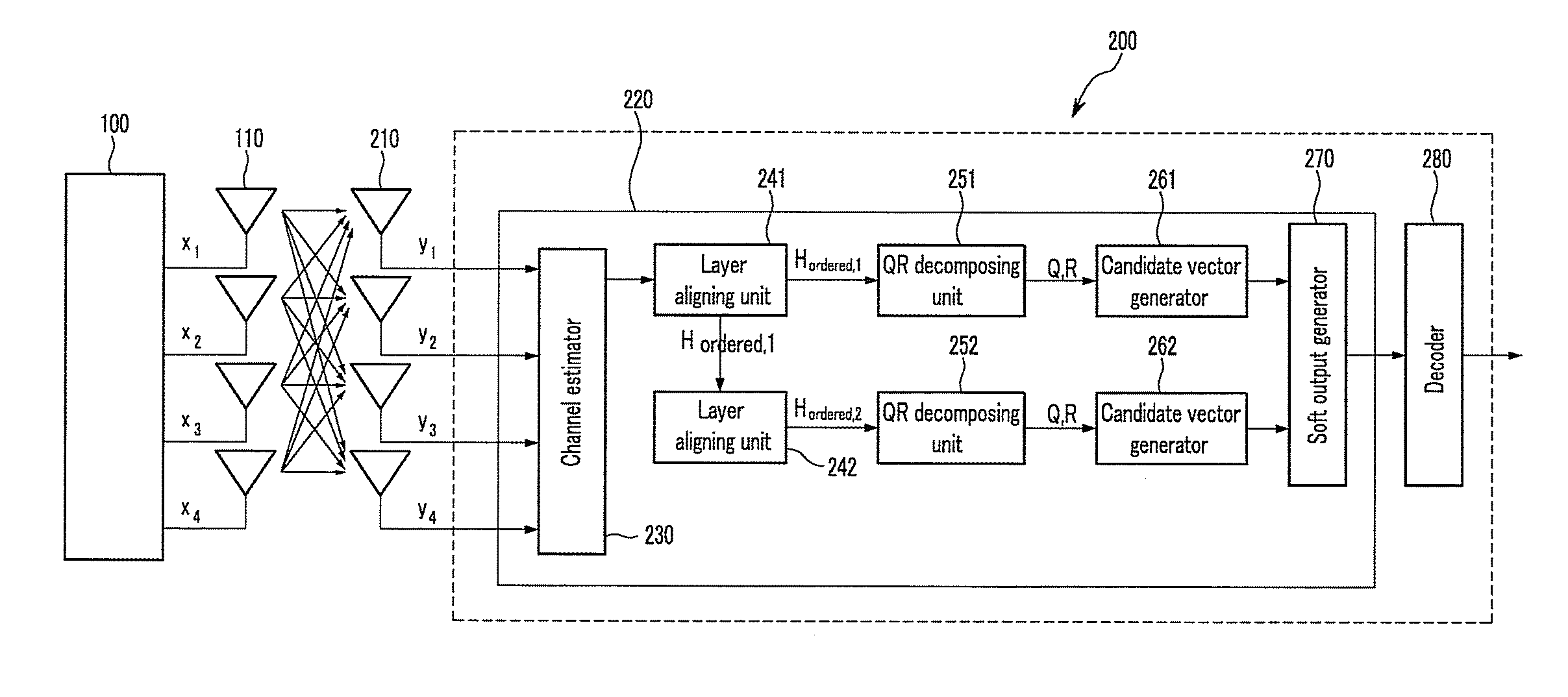
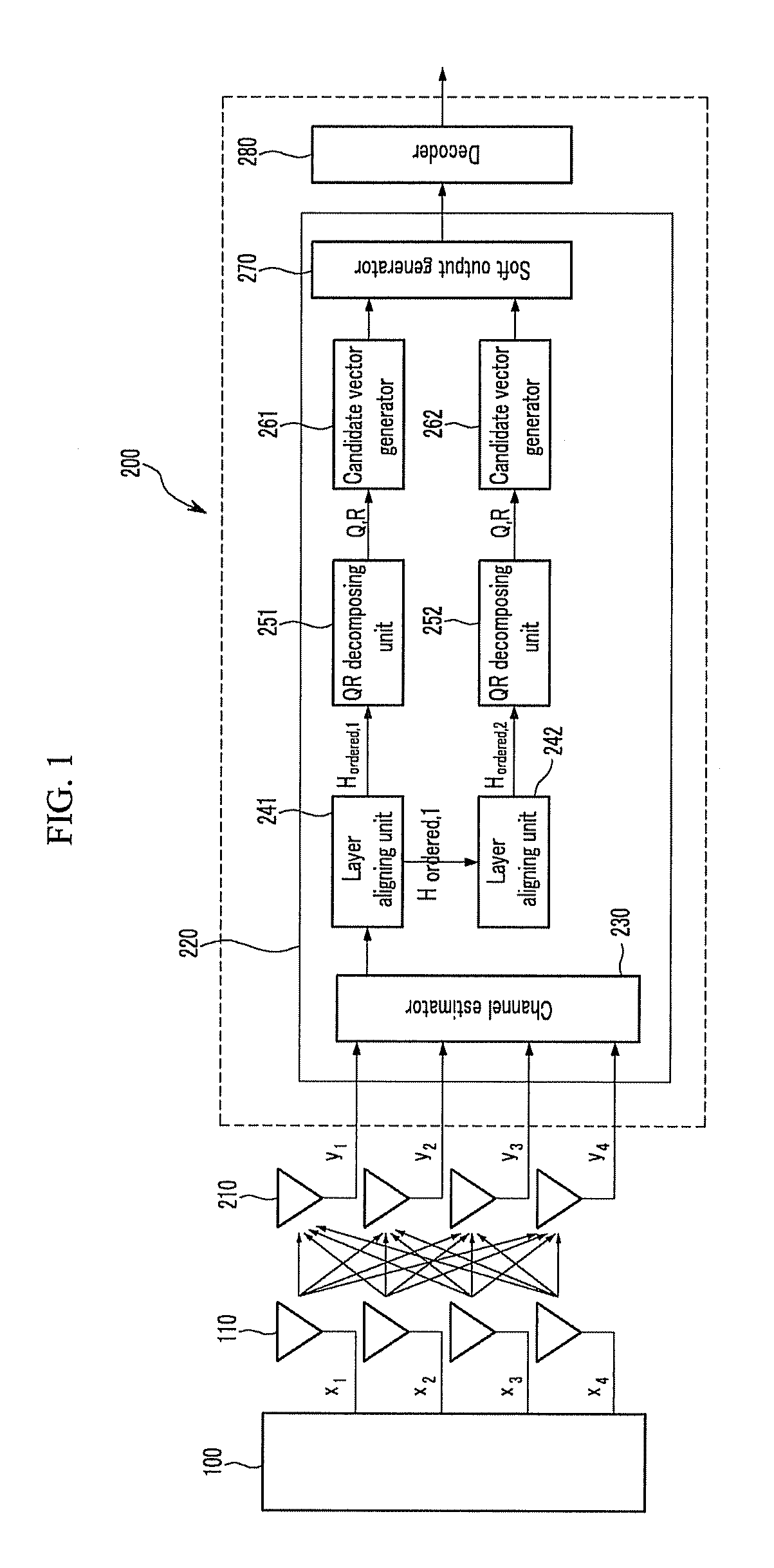
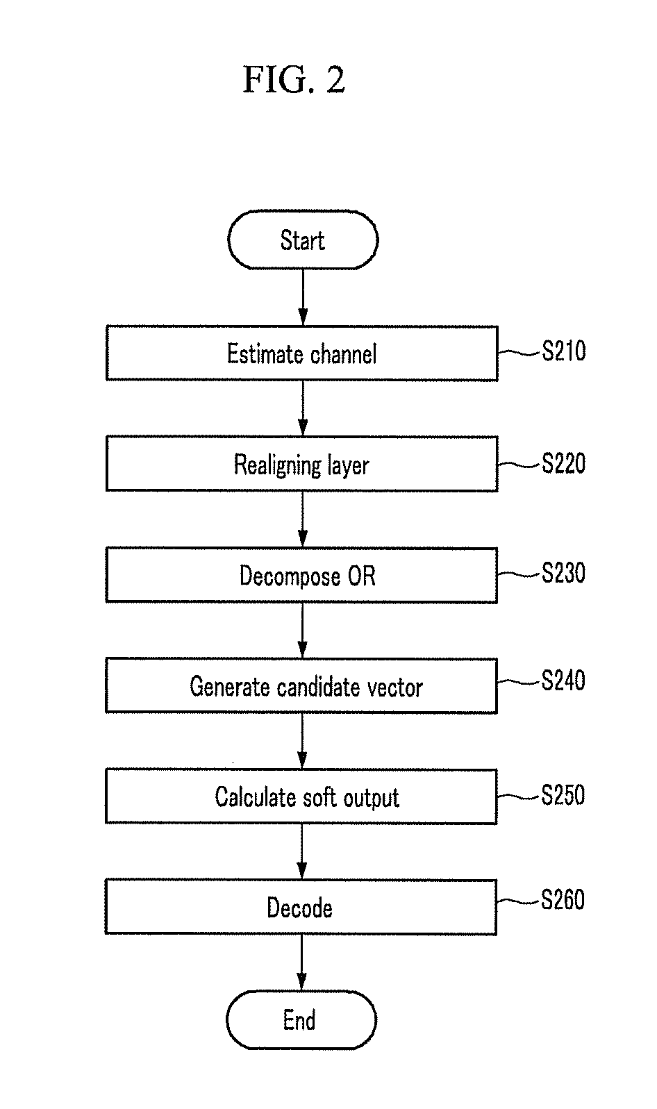
[0036]Hereinafter, a device for detecting a signal and a method for detecting a signal according to an exemplary embodiment of the present invention will be described with reference to the accompanying drawings....


PUM


Abstract

The present invention relates to a method for detecting a signal, a device for detecting a signal, and a receiving device. A method for detecting a signal according to the present invention is a method for detecting a signal from a receiving device in a communication system including a multi-output multi-input antenna, including: estimating a channel matrix of a signal received from a plurality of receiving antennas; generating at least one channel matrix groups by aligning the channel matrix and generating at least one transmitting signal group by aligning a transmitting signal to be estimated to correspond thereto; determining a first candidate vector in consideration of all constellation points for a first layer of the at least one transmitting signal group; determining a second candidate vector in consideration of all constellation points for a second layer of the at least one transmitting signal group; generating a final candidate vector including the first candidate vector and the second candidate vector; and calculating a soft output using the final candidate vector.

Description

CROSS-REFERENCE TO RELATED APPLICATION[0001]This application claims priority to and the benefit of Korean Patent Application No. 10-2009-0036496 filed in the Korean Intellectual Property Office on Apr. 27, 2009, the entire contents of which are incorporated herein by reference.BACKGROUND OF THE INVENTION[0002](a) Field of the Invention[0003]The present invention relates to a method for detecting a signal, a device for detecting a signal, and a receiving device.[0004](b) Description of the Related Art[0005]With the development of wireless communication systems, the demand for speed has increased. In order to meet the demand, a need exists for a use of a wide frequency bandwidth. However, frequency resources are limited. Therefore, as a method for transmitting more data while using a limited frequency bandwidth, a multi-input multi-output (MIMO) antenna technology has been used.[0006]The multi-input multi-output antenna technology is largely sorted into a spatial diversity scheme that...

Claims


Application Information

Patent Timeline
IPC IPC(8): H04L1/02
CPCH04L27/02H04B7/08H04L27/26
Inventor BAHNG, SEUNGJAEKIM, JUNGHYUNLEE, HOONPARK, YOUN OK
Owner ELECTRONICS & TELECOMM RES INST
Why Eureka
Try Eureka