Acoustic camera

a technology of acoustic camera and sound field imaging, applied in the field of acoustic camera, can solve the problems of increasing the difficulty of obtaining the sound field imaging of a noise source, and increasing the difficulty of obtaining the sound field imaging.

Inactive Publication Date: 2010-10-28
NAT CHIAO TUNG UNIV
View PDF6 Cites 24 Cited by
  • Summary
  • Abstract
  • Description
  • Claims
  • Application Information

AI Technical Summary

Benefits of technology

[0012]Another objective of the present invention provide an acoustic camera, which has two sets of microphone arrays, where a switch is used to shift the near-field mode and the far-field mode, whereby the acoustic camera can effectively obtain the sound field imaging of a noise source.
[0013]A further objective of the present invention provide an acoustic camera, which uses a delay-and-sum module and an acoustic inverse computation module to process sound field imaging, whereby the present invention can effectively reduce the amount of calculation and can position a noise source in realtime.
[0014]The present invention proposes an acoustic camera, which comprises a first sound pick-up device, a second sound pick-up device and a switch, where the switch respectively connects with the first sound pick-up device and the second sound pick-up device. The switch is used to select the first sound pick-up device or the second sound pick-up device to reconstruct the sound field of a detected object. The first sound pick-up device has a first microphone array, which is a uniform microphone array for a near-field sound field. The second sound pick-up device has a second microphone array, which is a non-uniform microphone array for a far-field sound field. The acoustic camera of the present invention adopts a delay-and-sum module, an acoustic inverse computation module and an acoustic post-processor to reconstruct the image of a sound field, whereby the present invention can effectively reduce the amount of calculation and can position a noise source in realtime. As the present invention optimizes the deployments of the first microphone array and second microphone array, the sound field imaging, which is undertaken by the delay-and-sum module, acoustic inverse computation module and acoustic post-processor, can achieve the best sound field identification. The acoustic camera of the present invention has two sets of microphone arrays, and a switch is used to shift the near-field sound field mode and the far-field sound field mode, whereby the present invention can effectively attain the sound field imaging of a noise source. The present invention provides the optimized deployments for the near-field and far-field microphone arrays, whereby the acoustic camera of the present invention has fine main lobes, few side lobes and none grating lobe when reconstructing the sound field of the sound source of a detected object.

Problems solved by technology

The current industry has a tendency toward high speed and high precision, and structural vibration thus becomes a more and more important problem.
However, all day long and all year round, the living environment is full of structural vibration-induced noise, which harms the physical and psychic health of people.
However, the prior art does not provide a wave-number-domain beam pattern or an optimization method to prove that the microphones thereof have the best deployment.
However, the U.S. Pat. No. 6,760,449B1 has a grating-lobe problem at high frequency, which is a result of lacking microphone deployment optimization.
Thus, the prior art is unlikely to identify a sound field in realtime (unlikely to position a noise source in realtime).
However, the U.S. Pat. No. 5,712,805 has a great error when applied to a planar noise source.
Besides, the prior art also has a disadvantage of needing a lot of microphones.
US2007 / 0189550A1 has the same disadvantage as the U.S. Pat. No. 6,958,950B2—needing a lot of microphones.

Method used


Image

  • Acoustic camera
  • Acoustic camera
  • Acoustic camera

Examples


Embodiment Construction

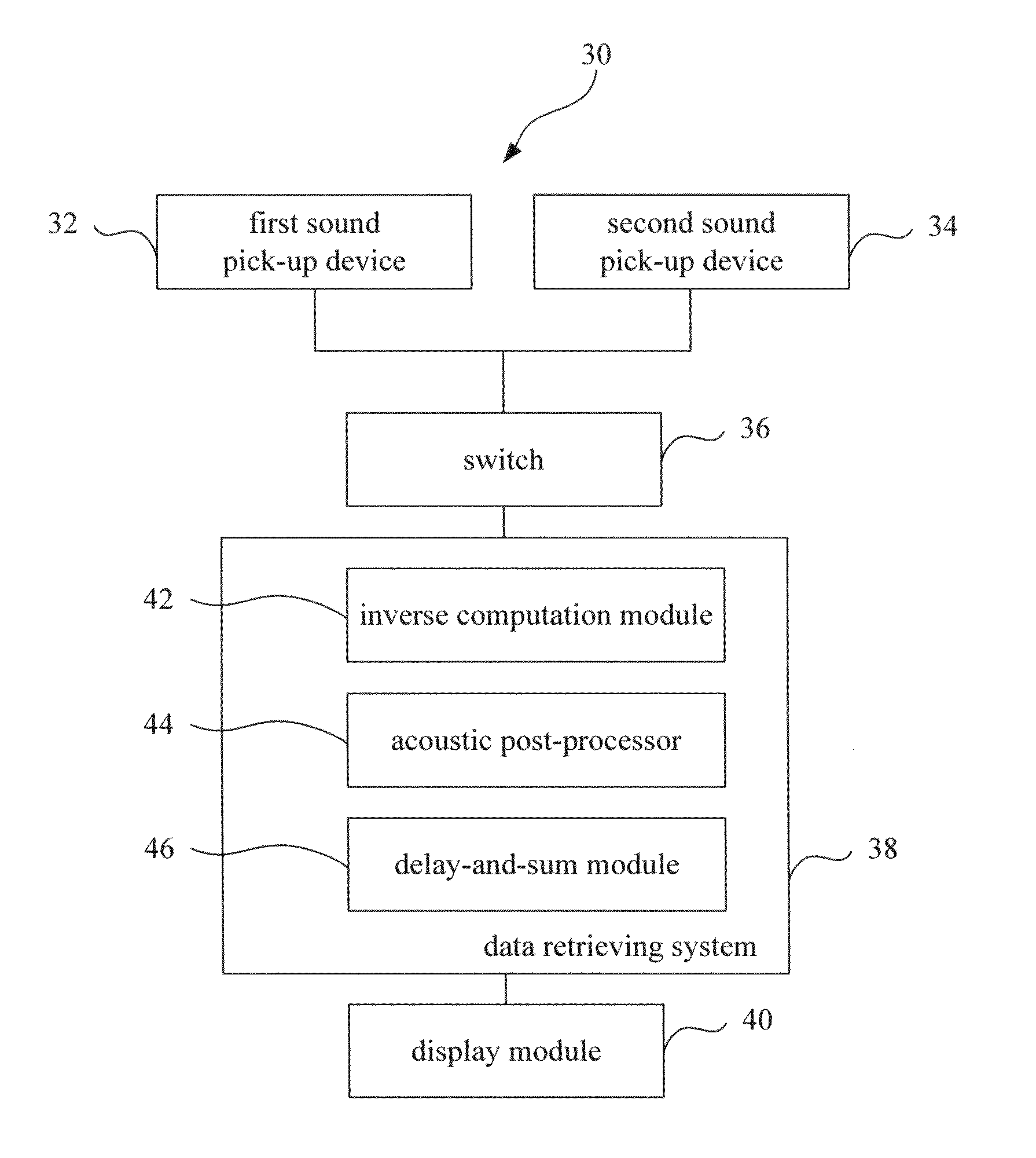
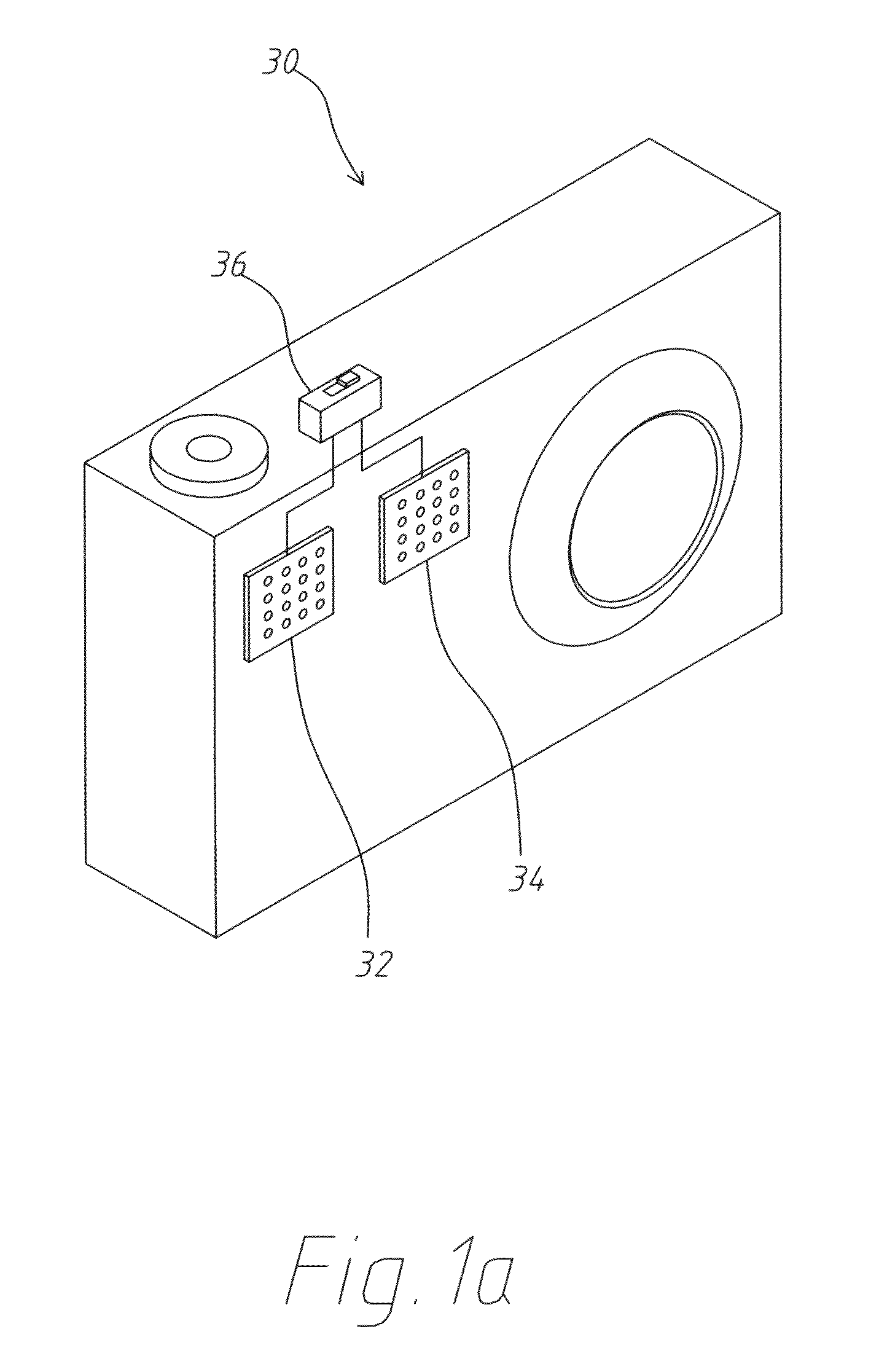
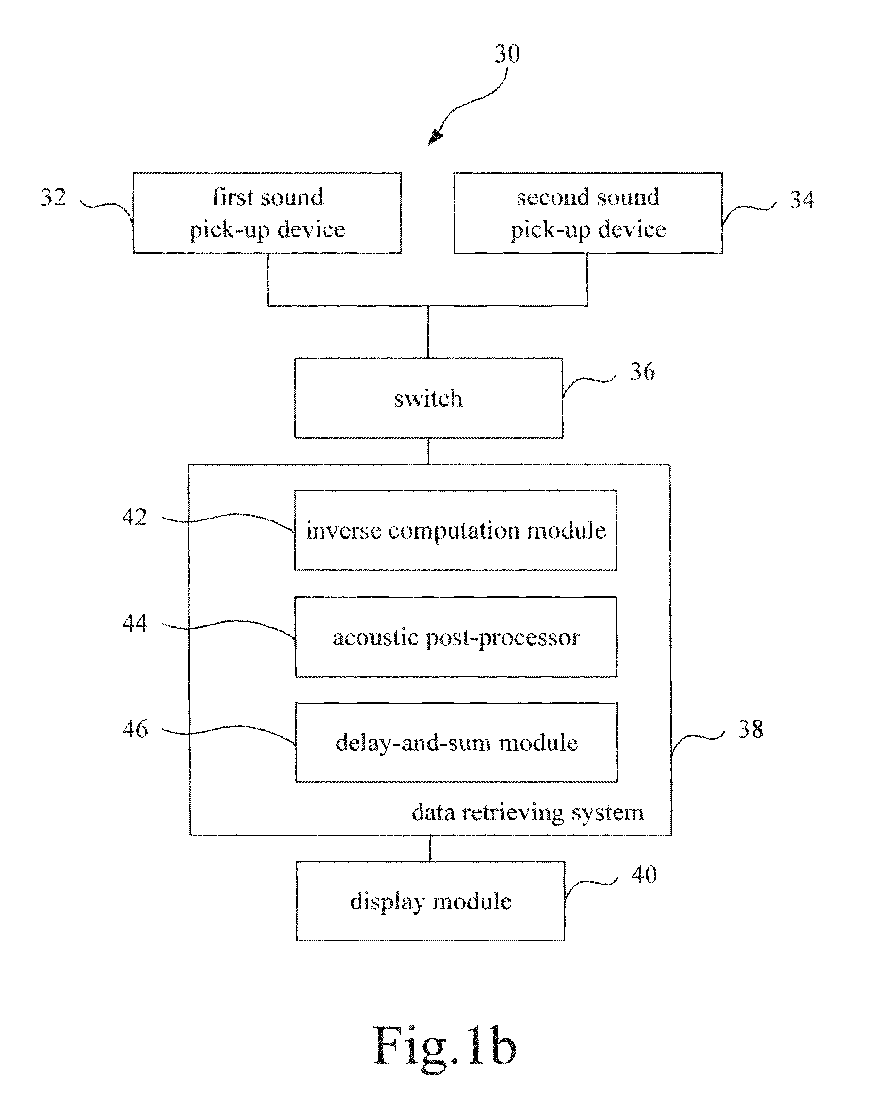
[0048]Refer to From FIG. 1a to FIG. 1d. One embodiment of the present invention proposes an acoustic camera 30 comprising a first sound pick-up device 32, a second sound pick-up device 34, a switch 36, a data retrieving system 38, and a display module 40. The first sound pick-up device 32 and the second sound pick-up device 34 are installed in the acoustic camera 30. In this embodiment, the first sound pick-up device 32 is a first microphone array containing a plurality of microphones, and the second sound pick-up device 34 is a second microphone array containing a plurality of microphones.

[0049]The switch 36 respectively connects with the first sound pick-up device 32 and the second sound pick-up device 34. The switch 36 is of a manual / mechanical type, a semi-automatic / electronic type, or an automatic / electronic type. The manual / mechanical type switch 36 is manually operated to select the first sound pick-up device 32 or the second sound pick-up device 34 to pick up the sound sourc...


PUM


Abstract

An acoustic camera comprises a first sound pick-up device, a second sound pick-up device, and a switch. The switch is respectively connected to the first sound pick-up device and the second pick-up device and used to select the first sound pick-up device or the second sound pick-up device to reconstruct the sound field of the sound source of a detected object. The first sound pick-up device has a first microphone array, and the first microphone array is a near-field uniform microphone array. The second sound pick-up device has a second microphone array, and the second microphone array is a far-field non-uniform microphone array.

Description

FIELD OF THE INVENTION[0001]The present invention relates to an acoustic camera, particularly to an acoustic camera using an optimal-deployment microphone array to pick up the sound source of a detected object.DESCRIPTION OF THE RELATED ART[0002]Vibration is an important research field and has developed for a long time. There are numerous researches about the related subjects, including vibration analysis, damping analysis, vibration control, and dynamic simulation. The current industry has a tendency toward high speed and high precision, and structural vibration thus becomes a more and more important problem.[0003]With the persistent advance of science and technology, people demand higher and higher living quality. However, all day long and all year round, the living environment is full of structural vibration-induced noise, which harms the physical and psychic health of people.[0004]The acoustic camera can effectively assist engineers to position a noise source or an abnormal soun...

Claims


Application Information

Patent Timeline
Patent Type & Authority Applications(United States)
IPC IPC(8): H04R3/00
CPCG03B42/06G01H3/125
Inventor BAI, MINGSIAN R.LIN, JIA-HONGLIU, KUAN-LIANG
Owner NAT CHIAO TUNG UNIV
Why Eureka
Try Eureka