Thermal-mechanical positioning for radiation tracking

Inactive Publication Date: 2010-11-04
SUNPOINT TECH
View PDF25 Cites 46 Cited by
  • Summary
  • Abstract
  • Description
  • Claims
  • Application Information

AI Technical Summary

Benefits of technology

[0008]There is therefore a need for a low cost, low maintenance, and high efficiency solar tracking system capable of tracking a radiation

Problems solved by technology

Such systems can be relatively expensive to manufacture and maintain, and may require access to a power grid, or require the use of a portion of the power generated by a solar element, in order to function, thereby reducing their efficiency.
Such systems may also require regular maintenance, possibly requiring the replacement of expensive and complex parts, in order to function over extended periods.
As a result, such active tracking systems are also generally expensive to manufacture and maintain, and provide limited utility in remote locations where, for example, regular maintenance and access to the materials needed for

Method used


Image

  • Thermal-mechanical positioning for radiation tracking
  • Thermal-mechanical positioning for radiation tracking
  • Thermal-mechanical positioning for radiation tracking

Examples


Embodiment Construction

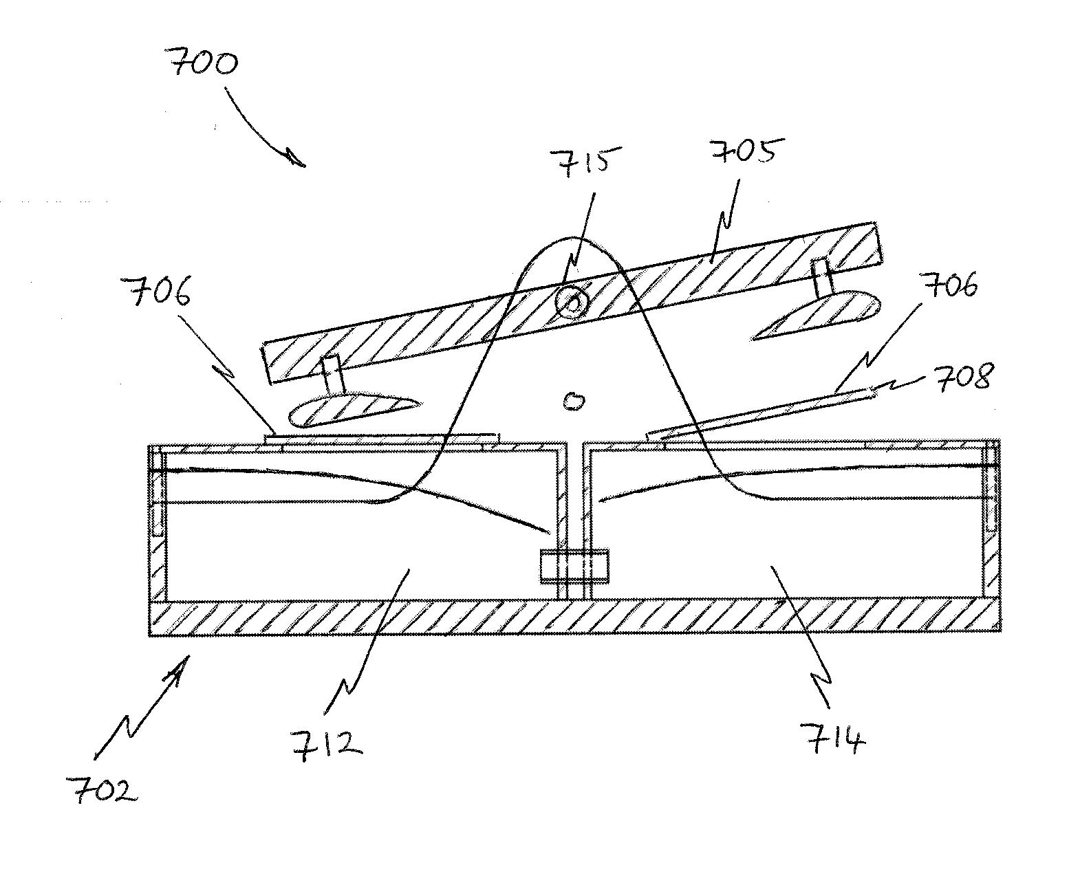
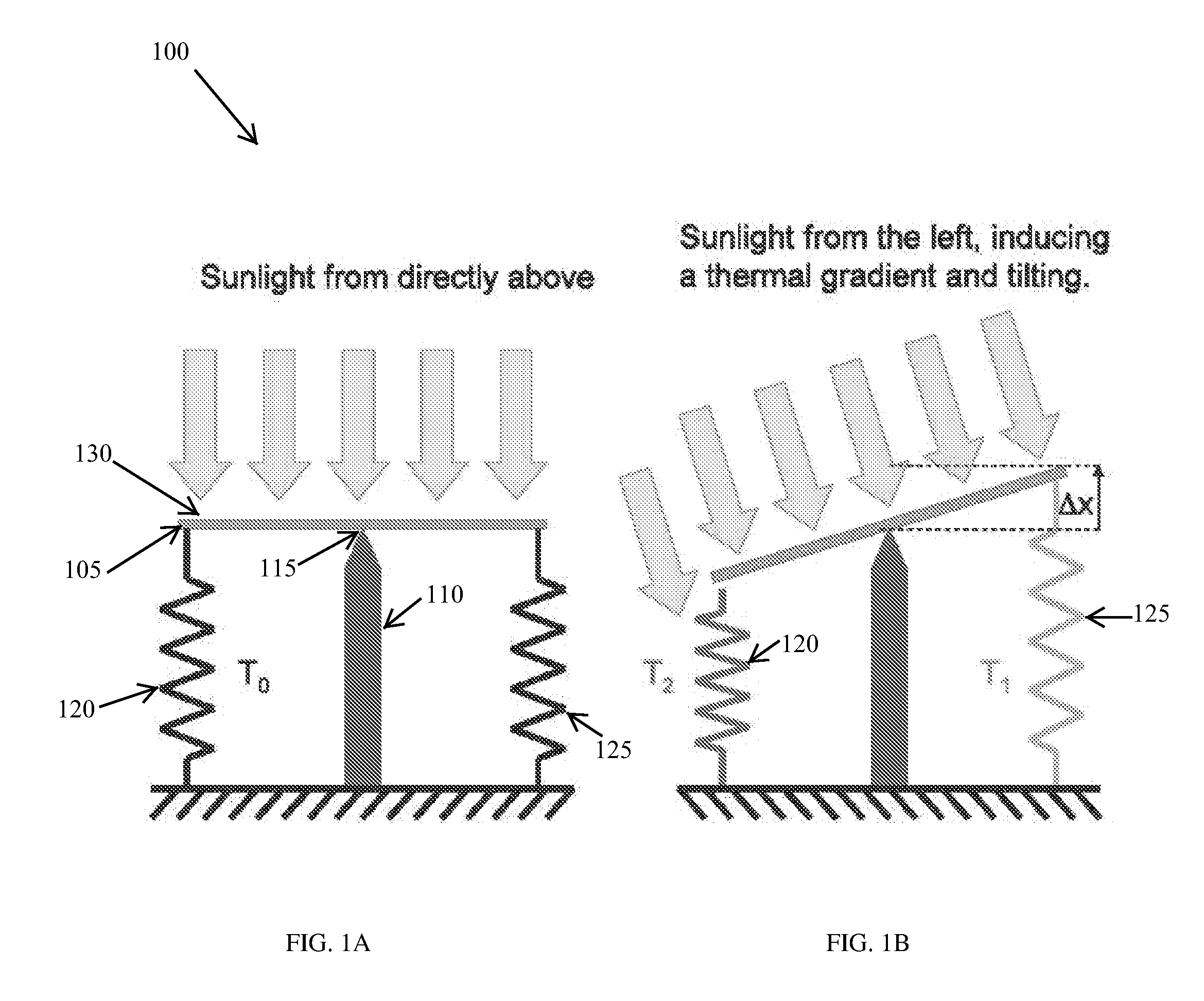
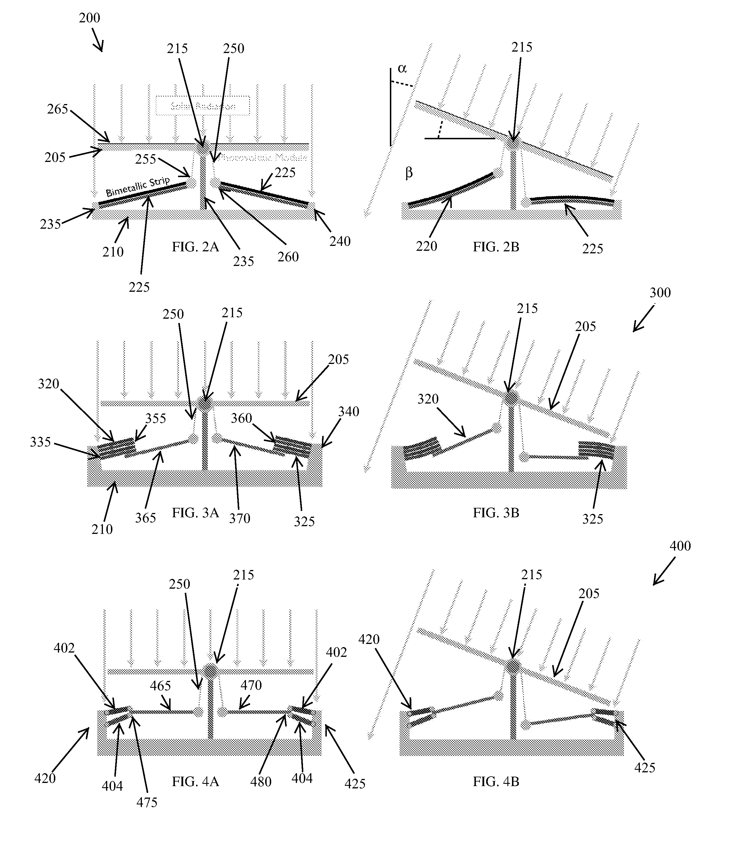
[0058]Various embodiments of the present invention provide for the tracking of a radiation source (e.g., the sun) utilizing a system for controlling the position and / or orientation of one or more solar panels, photovoltaic modules, collectors, and / or reflectors without the need for electric motors, photonic sensors, and / or electrical circuitry. In alternative embodiments, any appropriate solar element, measurement device, tracking device, and / or combination thereof, may be utilized with the tracking systems and methods described herein. In some instances, certain conventional powered elements and controls may be utilized in combination with the passive systems described herein, to achieve a combined benefit, albeit at much lower power consumption levels than would be attainable without the addition of the passive system components.

[0059]In contrast to systems requiring electrically powered actuation for tracking, the passive systems and methods described herein utilize one or more e...


PUM


Abstract

The invention relates to systems and methods for controlling angular position of a pivotable platform relative to a radiation source. In one embodiment, an apparatus for controlling angular position of a pivotable platform relative to a radiation source includes a frame, a thermal actuation element coupled to the frame, a pivotable platform positioned between the radiation source and the thermal actuation element so as to at least partially block energy from the radiation source from impinging on the thermal actuation element, and apparatus for pivoting the pivotable platform in response to a thermally controlled deformation of the thermal actuation element.

Description

CROSS-REFERENCE TO RELATED APPLICATIONS[0001]This application claims priority to and the benefit of U.S. provisional patent application Ser. No. 61 / 174,278 filed Apr. 30, 2009, the disclosure of which is incorporated herein by reference in its entirety.FIELD OF THE INVENTION[0002]The present invention relates generally to the field of thermal radiation tracking and, more particularly, to combined thermo-mechanical systems, and related methods, that can be used to track a thermal radiation source for use in energy production systems utilizing solar power.BACKGROUND OF THE INVENTION[0003]The solar industry has experienced rapid growth in recent years as the levelized costs of electricity (LCOE) associated with the generation of energy through solar power systems has decreased to the point that it is approaching grid parity. As a result, electrical utilities have become increasingly interested in the development of solar power generation systems for incorporation into energy grids.[000...

Claims


Application Information

Patent Timeline
IPC IPC(8): F24J2/38F24J2/52F24S50/20
CPCF24J2/38F24J2/40F24J2/402F24J2/405F24J2/4638F24J2/541H02S20/00F24J2002/508F24J2002/5437F24J2002/5458Y02E10/47Y02E10/50F24J2002/075F24S30/425F24S40/85F24S50/00F24S50/20F24S50/40F24S50/60F24S80/56F24S2020/23F24S2030/11F24S2030/133H02S20/32
Inventor BATHURST, STEPHEN P.CARVEY, ANDREW W.COHEN, ERIC D.ETRA, JORDAN V.LIAU, FORREST W.WHITFIELD, GEORGE C.
Owner SUNPOINT TECH
Why Eureka
Try Eureka