Photovoltaic Conversion Assembly with Concentrating Optics

a technology of concentrating optics and conversion assembly, which is applied in the direction of basic electric elements, electrical apparatus, semiconductor devices, etc., can solve the problems of re-emitted light being often too high for transmission within the slab to the pv cell, light simply passing out of the slab through the first major surface and is wasted, and re-emitted light often escapes from the optical slab via its first major surfa

Inactive Publication Date: 2010-11-04
ENERGY FOCUS INC
View PDF3 Cites 18 Cited by
  • Summary
  • Abstract
  • Description
  • Claims
  • Application Information

AI Technical Summary

Benefits of technology

[0007]Beneficially, the two-way spectrally selective reflector cooperates with the down-converting structure to retain high angle light in the optical slab from the down-converting structure. This increases the light transmitted within the optical slab to the PV cells.

Problems solved by technology

A drawback of the foregoing photovoltaic conversion assembly is that the re-emitted light is often at an angle too high for transmission within the slab to the PV cells at the endges.
Such light simply passes out of the slab through the first major surface and is wasted.
A drawback, similar to that mentioned above for the first-mentioned prior art assembly, is that re-emitted light often escapes from the optical slab via its first major surface.
A further drawback is that re-emitted light is susceptible being re-absorbed or scattered by the dye, etc. interspersed in the optical slab, further reducing the light reaching the PV cells.
Such light is wasted.

Method used


Image

  • Photovoltaic Conversion Assembly with Concentrating Optics
  • Photovoltaic Conversion Assembly with Concentrating Optics
  • Photovoltaic Conversion Assembly with Concentrating Optics

Examples


Embodiment Construction

[0024]Various embodiments of the inventive photovoltaic conversion assemblies are described, with the most preferred embodiment described last. In this specification, like-named parts have the same structure or property. This description covers the three sections of (1) Prior Art and Inventive Embodiment, (2) Definitions of Claim Terms, and (3) Other Embodiments.

(1) Prior Art and Inventive Embodiment

[0025]To place the invention in perspective, two prior art photovoltaic conversion assemblies are described before describing an inventive embodiment.

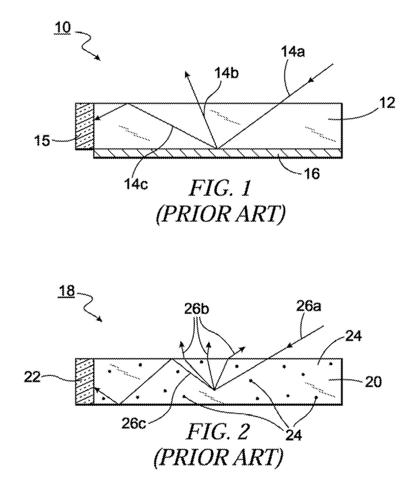
[0026]FIG. 1 shows a prior art photovoltaic conversion assembly 10. Assembly 10 includes an optical slab 12 for receiving incoming light, such as 14a, with the goal of transmitting the light to a photovoltaic (PV) cell 15. Incoming light 14a passes through optical slab 12 and is received by a down-converting means 16, such as a phosphor-containing layer. Down-converting means 16 absorbs light at one energy level, and re-emits light, such as...


PUM


Abstract

A photovoltaic conversion assembly comprises an optical slab with first and second major surfaces and an intermediate surface therebetween. Light energy to be collected impinges as incoming photons on the first major surface. At least one PV cell is mounted to receive light energy from the intermediate surface of the optical slab and convert such light energy to electrical energy. The PV cell has a highest band gap E. A down-converting structure is located on the second major surface of the slab for converting to lower energy light received through the slab, with at least about 75 percent of the converted light having an energy level above the band gap E. A two-way spectrally selective reflector, located proximate the first major surface, cooperates with the down-converting structure for preventing high angle light from undesirably exiting the optical slab via the first major surface.

Description

FIELD OF THE INVENTION[0001]The present invention relates to a photovoltaic conversion assembly with integrated concentrating optics.BACKGROUND OF THE INVENTION[0002]In an effort to increase the efficiency of conversion of solar or other light energy to electricity, photovoltaic conversion assemblies with integrated concentrating optics have been proposed. One such prior art photovoltaic conversion assembly includes an optical slab formed into a rectangular solid, and serving as concentrating optics to provide concentrated light to one or more PV cells. A “first major surface”—as used herein—of the slab receives solar or other light energy and a second major surface is provided with a phosphor layer for absorbing photons that pass through the slab and for re-emitting photons at a lower energy. The one or more PV cells are mounted to edges of the slab formed between the first and second major surfaces.[0003]A drawback of the foregoing photovoltaic conversion assembly is that the re-e...

Claims


Application Information

Patent Timeline
Patent Type & Authority Applications(United States)
IPC IPC(8): H01L31/00
CPCH01L31/055H01L31/0547Y02E10/52
Inventor BUELOW II, ROGER F.
Owner ENERGY FOCUS INC
Why Eureka
Try Eureka