Data display device, integrated circuit, data display method, data display program, and recording medium
Inactive Publication Date: 2010-11-04
PANASONIC CORP
11 Cites 235 Cited by
AI-Extracted Technical Summary
Problems solved by technology
On the other hand, when a large amount of image data is saved on a recording medium, a user has to spend a significant amount of...
View moreMethod used
[0146]Thus switching the scrolling speed for each cluster allows the user to easily achieve an understanding of a grouping of photographic image data. It also makes viewing photographic image data and searching for a desired image easy and efficient.
[0169]The thumbnails for photographic image data included in a cluster are thus displayed overlapping each other, without overlapping the photographic image data included in a different cluster. This allows the user to easily achieve an understanding of a grouping of photographic image data. It also makes viewing photographic image data and searching for a desired image easy and efficient.
[0207]In embodiment 3, the user can enjoy a panoramic view of changes in multiple groups of photographic image data. Furthermore, the user can simultaneously view changes in the same group of photographic image data under differing conditions. Accordingly, it is easier for the user to recognize the difference between pieces of photographic image data. This also makes viewing photographic image data and searching for a desired image easier and more efficient.
[0230]In embodiment 4, the user can simultaneously and visually view changes in attribute information for the cluster that includes the pieces of photographic image data for the thumbnail sequence being scrolled. Therefore, the user can more easily achieve an understanding of a grouping of photographic image data. This also makes viewing photographic image data and searching for a desired image easier and more efficient.
[0246]FIGS. 21A and 21E are provided as an example of variable control of the scrolling speed within a cluster. FIGS. 21A and 21B show the scrolling speed within one cluster. FIG. 21A is an example of variable control in which the scrolling speed for the beginning and the end of a cluster display period is changed along a line representing a direct function, whereas FIG. 21B is an example of variable control in which the scrolling speed for the beginning and the end of a cluster display period is changed along a line representing a quadratic function. Note that it is preferable that the scrolling speed ...
View moreBenefits of technology
[0017]With each of the above-described data display device, integrated circuit, data display method, data display program and recording medium, the user can view and search file data while recognizing groups of file data in accordance with a grouping condition. The user can thereby easily and efficiently view file data or search for a desired piece of file data.
[0018]In the data display device, the control unit may display by scrolling, on the display unit, the group of images related to the pieces of file data while controlling a scrolling speed for each cluster.
[0019]With this structure, the user can easily achieve an understanding, via changes in scrolling s...
View moreAbstract
A data display device for displaying, on a display unit, a group of images related to a plurality of pieces of file data comprises: an operation unit operable to receive, from a user, a display operation pertaining to the group of images related to the pieces of file data; a storage unit storing cluster information on clusters that are generated by grouping the pieces of file data according to a grouping condition; and a control unit operable to display, on the display unit, the group of images related to the pieces of file data so that the user can distinguish between clusters, in accordance with the display operation received by the operation unit and with the cluster information stored in the storage unit.
Application Domain
Technology Topic
Image
Examples
- Experimental program(4)
Example
[0087]Embodiment 1 of the present invention is described below with reference to the drawings.
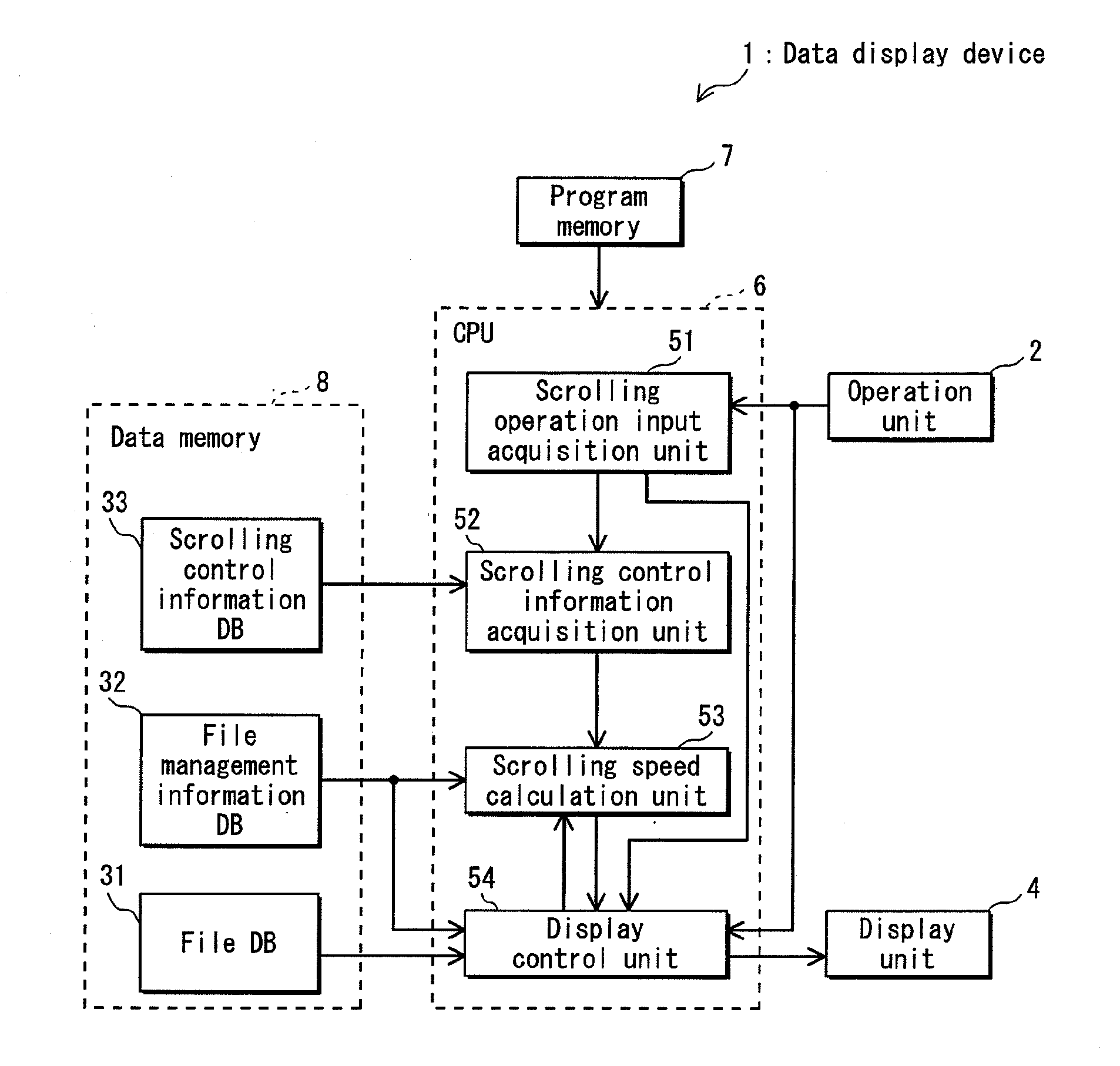
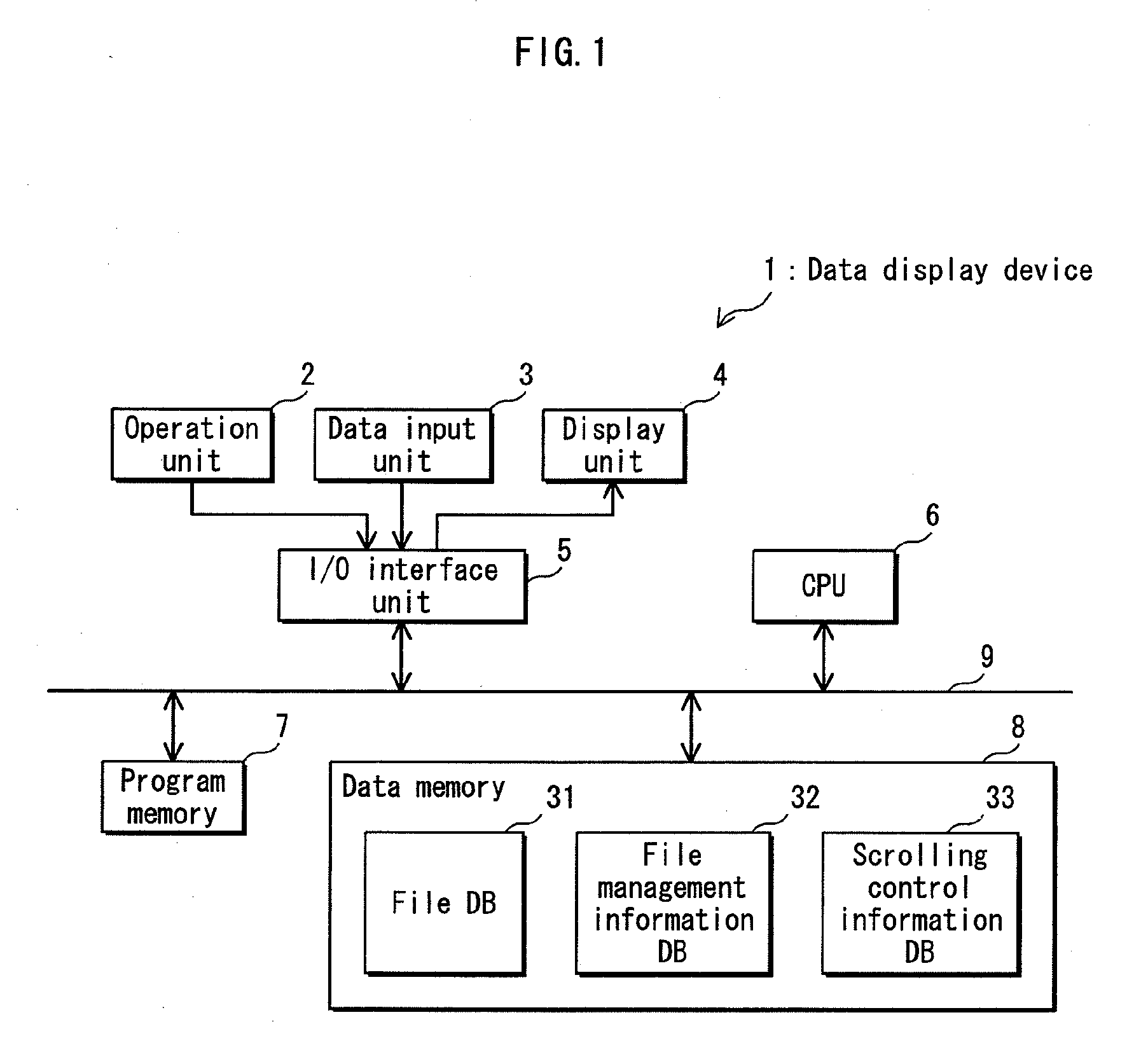
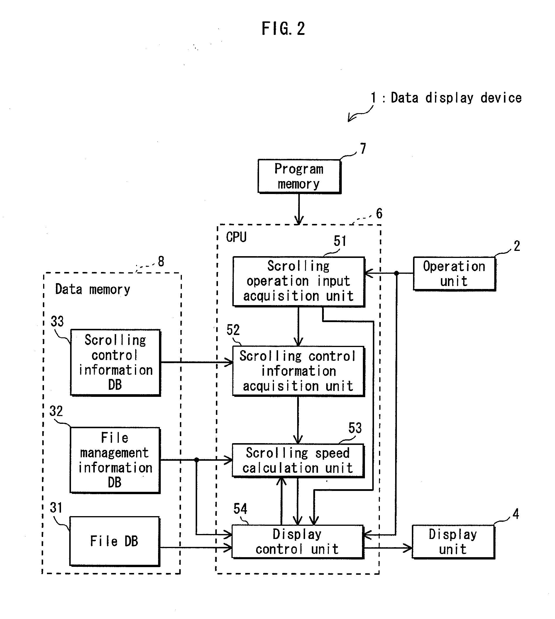
[0088]FIG. 1 is a hardware block diagram of a data display device according to embodiment 1, and FIG. 2 is a functional block diagram of the data display device in FIG. 1. In FIG. 2, however, the CPU 6 is shown directly connected to the operation unit 2, display unit 4, program memory 7, and data memory 8, and the data input unit 3, I/O interface unit 5, and bus 9 are omitted. Note that the data display devices in other embodiments have substantially the same hardware configuration as in FIG. 1. Furthermore, the functional block diagrams for the other embodiments are similarly simplified.
[0089]The data display device 1 comprises an operation unit 2, data input unit 3, display unit 4, I/O interface unit 5, central processing unit (CPU) 6, program memory 7, data memory 8, and bus 9.
[0090]The operation unit 2 is a device for the user to operate the data display device 1 and to manipulate data displayed on the display unit 4 of the data display device 1. The operation unit 2 includes, for example, keys, switches, a touchpad or touch panel, etc. The data input unit 3 is a device for inputting file data such as photographic image data, dynamic image data such as video, music data, etc. into the data memory 8. The display unit 4 is a display device that includes, for example, a liquid crystal display or the like. A touch panel constituting the operation unit 2 is provided above the display screen. The I/O interface unit 5 is an interface that performs input and output processing on data between the operation unit 2, data input unit 3, and display unit 4 on the one hand and the CPU 6 on the other.
[0091]The CPU 6 controls the entire data display device 1 and performs computation, makes logical decisions, etc. for each type of processing. For example, the CPU 6 controls input and output processing of data by the I/O interface unit 5 and executes the display control processing indicated by the operation flow in FIG. 8.
[0092]The program memory 7 stores a variety of control programs for controlling the data display device 1 and a variety of application programs. For example, the program memory 7 stores a viewer application program for viewing the data, the viewer application program describing the procedures shown in the operation flow in FIG. 8. In addition to a file database 31, file management information database 32, and scrolling control information database 33, the data memory 8 stores, for example, data produced by each of the processes in the CPU 6. The program memory 7 and data memory 8 are storage devices including a large capacity media disc, e.g. a hard disk drive (HDD), digital versatile disc (DVD), etc., and a semiconductor memory.
[0093]The bus 9 transfers control signals for controlling each constituent element and data that is exchanged between each constituent element.
[0094]
[0095]FIG. 3(a) and (b) shows examples of screens displayed by the display unit 4 in FIG. 1. In the examples in FIG. 3(a) and (b), the file data is photographic image data. Note that the file data is also photographic image data in the other examples of display screens.
[0096]In the examples in FIG. 3(a) and (b), an album library 11, thumbnail display area 12, menu buttons 13, size scrollbar 14, display position scrollbar 15, right button 16, and left button 17 are displayed. Note that the touch panel constituting the operation unit 2 is provided above the display screen of the display unit 4.
[0097]The album library 11 is composed of a layered folder representing, for example, photo albums. Each photo album is a single folder or the like in which multiple pieces of photographic image data are saved. The user can select a desired folder by touching a folder displayed in the album library 11. A bold frame is displayed around the selected folder (in the examples in FIG. 3(a) and (b), the folder “A01”), and thumbnail images of the photographic image data in the selected folder are displayed in the thumbnail display area 12. Note that, while not shown in the figures, buttons for scrolling up and down are provided in the album library 11. The user can push these buttons to change the folders displayed in the album library 11.
[0098]The thumbnail display area 12 is an area for displaying thumbnails for the photographic image data in the selected folder. One thumbnail is shown in FIGS. 3(a), and 12 in (b). The menu buttons 13 are buttons that, for example, select an image as a favorite, rotate a selected image to the left or right, select slideshow playback, etc.
[0099]The size scrollbar 14 is a scrollbar to change the number of thumbnails displayed in the thumbnail display area 12. A slider 14a that the user uses to change the number of thumbnails displayed is provided in the size scrollbar 14. By sliding the slider 14a to the left or right, the user can switch between the display screen displaying one thumbnail shown in FIG. 3(a) and the display screen displaying 12 thumbnails shown in (b).
[0100]The display position scrollbar 15 is a scrollbar for changing the position of the photographic image data that is shown in the display screen and is arranged, for example, in order of time of photography. A slider 15a that the user uses to change the position of the displayed photographic image data is provided in the display position scrollbar 15.
[0101]The right button 16 is, for example, a button to scroll the series of thumbnails one column from right to left, and the left button 17 is, for example, a button to scroll the series of thumbnails one column from left to right.
[0102]
[0103]FIG. 4(a), (b), and (c) illustrates an example of scrolling using the operation unit 2 in FIG. 1.
[0104]On the display screen in FIG. 4(a), the series of thumbnails is not in motion. When the series of thumbnails is not in motion, the user can cause the thumbnail sequence to scroll from the right to the left (the direction of the arrow 18 in FIG. 4(a)) by moving his finger from the right to the left while touching the touch panel located above the display screen. Via this scrolling operation, the thumbnail sequence on the display screen of the display unit 4 scrolls from right to left, changing successively from FIG. 4(a) to (b) and (c).
[0105]Conversely, to cause the thumbnail sequence to scroll from the left to the right, the user moves his finger from the left to the right while touching the touch panel located above the display screen. In this example, the user performs a scrolling operation while the thumbnail sequence is not in motion, yet the user may perform scrolling operations while the thumbnail sequence is scrolling.
[0106]Note that hereinafter, the distance from where the user touches the touch panel at the start of a scrolling operation to where the user's finger stops touching the touch panel at the end of the scrolling operation is referred to as the “operation distance”. The acceleration of the user's finger from the start to the end of the scrolling operation is referred to as “operation acceleration”. The direction from the start to the end of the scrolling operation is referred to as the “scrolling direction”.
[0107]
[0108]The file database (hereinafter “file DB”) 31 is a database for storing the pieces of file data input from the data input unit 3.
[0109]The file management information database (hereinafter “file management information DB”) 32, an example of which is shown in FIG. 5, is a database for storing file management information such as attribute information, cluster information, etc. on the file data stored in the file DB 31. FIG. 5 shows an example configuration of the file management information DB 32 in FIG. 1 when file data is photographic image data.
[0110]In the file management information DE 32, for each piece of photographic image data, a uniquely assigned file ID is associated with a file name for the piece of photographic image data, information on time of photography indicating when the photographic image was captured, and a cluster layer. While not shown in the figure, folder information is also stored in the file management information DB 32 for the photographic image data for each file ID.
[0111]In general, clusters are a collection of data resulting when data is divided according to certain conditions. For example, clusters may be a collection of photographic image data organized by events, such as a trip, an entrance ceremony, etc.
[0112]The clusters in this embodiment are a collection of photographic image data divided based on the distance between the information on time of photography for the photographic images. In the example in FIG. 5, four layers of clusters have been created based on the distance between the information on time of photography for the photographic images in the photographic image data. However, a known method of clustering may be used, such as Ward's method using mean Euclidean distance, the centroid method, or the median method.
[0113]FIG. 6 schematically shows, for photographic image data, cluster layers based on information on time of photography in the file management information DB 32 in FIG. 5. Note that in FIG. 6, “ID1” represents a piece of photographic image data whose file ID is “1”.
[0114]In cluster layer “1”, each piece of photographic image data is in a different cluster. In cluster layer “2”, the pieces of photographic image data surrounded by a solid line form one cluster. In cluster layer “3”, the pieces of photographic image data surrounded by a dashed line form one cluster. In cluster layer “4”, the pieces of photographic image data surrounded by an alternating long and short dashed line form one cluster. In FIG. 5, the cluster layer corresponding to each piece of photographic image data indicates the highest of the cluster layers in which the piece of photographic image data is the top piece in the cluster.
[0115]The scrolling control information database (hereinafter “scrolling control information DB”) 33, an example of which is shown in FIG. 7, is a database for recording scrolling control information that controls the speed of a scrolling display. FIG. 7 shows an example configuration of the scrolling control information DB 33 in FIG. 1.
[0116]In the scrolling control information DB 33, a standard scrolling speed and a cluster layer level are associated with an operation distance and an operation acceleration. The operation distance and operation acceleration are as described above. The standard scrolling speed indicates the standard scroll speed for the scrolling display, and the cluster layer level indicates the cluster layer for showing the user a grouping of pieces of photographic image data. For example, when the cluster layer level is “2”, the scrolling speed is controlled for clusters in cluster layer “2”.
[0117]
[0118]From the program memory 7, the CPU 6 reads a viewer application program that describes the procedures shown in the operation flow in FIG. 8 and executes the viewer application program that has been read. The CPU 6 thereby functions as a scrolling operation input acquisition unit 51, scrolling control information acquisition unit 52, scrolling speed calculation unit 53, and display control unit 54.
[0119]Based on the operation signal input from the operation unit 2 via the I/O interface unit 5 and bus 9, the scrolling operation input acquisition unit 51 acquires the scrolling direction, operation distance, and operation acceleration for a scrolling operation by the user. The scrolling operation input acquisition unit 51 outputs the acquired scrolling direction to the display control unit 54 and the acquired operation distance and operation acceleration to the scrolling control information acquisition unit 52.
[0120]The scrolling control information acquisition unit 52 refers to the contents stored in the scrolling control information DB 33 to acquire the standard scrolling speed and cluster layer level associated with the operation distance and operation acceleration input from the scrolling operation input acquisition unit 51. The scrolling control information acquisition unit 52 outputs the acquired standard scrolling speed and cluster layer level to the scrolling speed calculation unit 53.
[0121]Folder information indicating the folder selected by the user is input into the scrolling speed calculation unit 53 from the display control unit 54, and the standard scrolling speed and cluster layer level are input into the scrolling speed calculation unit 53 from the scrolling control information acquisition unit 52. For the folder selected by the user, the scrolling speed calculation unit 53 calculates the scrolling speed for each cluster at the cluster layer level based on the standard scrolling speed and cluster layer level, outputting the scrolling speed for each cluster to the display control unit 54. However, the scrolling speed calculation unit 53 calculates the scrolling speed for each cluster so that the display time of each cluster remains constant.
[0122]The following is an explanation of a method for calculating the scrolling speed of a cluster. Note that for the sake of simplicity, the distance between thumbnails is assumed to be zero.
[0123]For each piece of photographic image data, the scrolling speed calculation unit 53 refers to the folder information (not shown in FIG. 5, as described above) in the file management information DB 32, thus acquiring “L”, the total number of pieces of photographic image data in the folder selected by the user. The scrolling speed calculation unit 53 multiplies the width of thumbnails “d” by “L” and divides the result “dL” by the standard scrolling speed “V”. The scrolling speed calculation unit 53 thereby calculates “dL/V”, the time necessary to display thumbnails for the entire photographic image data in the folder selected by the user (hereinafter “total display time”) when the display scrolls at the standard speed “V”.
[0124]Next, for each piece of photographic image data, the scrolling speed calculation unit 53 refers to the folder information and cluster layer in the file management information DB 32 to acquire “M”, the number of clusters at the cluster layer level in the folder selected by the user. The scrolling speed calculation unit 53 divides the total display time “dL/V” by the number of clusters “M”, thereby calculating “dL/(VM)=TA”, i.e. the time for scrolling through one cluster (hereinafter “cluster display time”).
[0125]Furthermore, the scrolling speed calculation unit 53 performs the following processes for each cluster in the cluster layer level. For each piece of photographic image data, the scrolling speed calculation unit 53 refers to the folder information and cluster layer in the file management information DB 32, thus acquiring “NA”, the number of pieces of photographic image data in a cluster. The scrolling speed calculation unit 53 multiplies the width of thumbnails “d” by “NA” and divides the result “NAd” by the cluster display time TA. The scrolling speed calculation unit 53 thereby calculates “NAd/TA=VA”, the cluster scrolling speed.
[0126]This method of calculating scrolling speed is only an example, however, and the method is not limited in this way. For example, in the above-described method of calculating scrolling speed, division by the thumbnail width “d” may be omitted.
[0127]An operation signal is input into the display control unit 54 from the operation unit 2 via the I/O interface unit 5 and the bus 9, and the display control unit 54 switches the display screen on the display unit 4 in accordance with the operation signal. For example, when the user selects a folder in the album library 11, the display control unit 54 displays a bold frame around the selected folder, displays thumbnails for the photographic image data in the selected folder in the thumbnail display area 12, and outputs folder information for the folder selected by the user to the scrolling speed calculation unit 53.
[0128]The scrolling direction is also input into the display control unit 54 from the scrolling operation input acquisition unit 51, and the scrolling speed for each cluster is input into the display control unit 54 from the scrolling speed calculation unit 53. While referring to the file management information DB 32, as it reads the photographic image data in the selected folder from the file DB 31, the display control unit 54 scrolls, on the display unit 4, the thumbnail sequence for photographic image data in the selected folder. The thumbnail sequence is scrolled in the scrolling direction and at the scrolling speed for each cluster.
[0129]Note that the scrolling speed of the thumbnail sequence displayed in the thumbnail display area 12 may be, for example, the scrolling speed of the cluster corresponding to the thumbnail located in the middle of the thumbnail display area 12, the scrolling speed of the cluster whose thumbnails have the largest display area in the thumbnail display area 12, the scrolling speed of the cluster with the most thumbnails shown on the thumbnail display area 12, etc.
[0130]
[0131]FIG. 8 is a flowchart showing the flow of display control processing by the CPU 6 in FIG. 1. Note that the user selects a folder or performs a scrolling operation on the touch panel provided above the display screen of the display unit 4 in order, for example, to peruse photographic image data, to search for a desired piece of photographic image data, to change the scrolling speed, etc.
[0132]The display control unit 54 receives an operation signal from the operation unit 2 and, based on the received operation signal, determines whether the user operation is a folder selection operation (step S1). If the user operation is not a folder selection operation (S1: NO), the processing in step S3 is performed. On the other hand, if the user operation is a folder selection operation (S1: YES), then based on the acquired operation signal, the display control unit 54 switches the display on the display unit 4 to the contents of the folder the user selected (step S2). The processing in step S1 is then performed.
[0133]The scrolling operation input acquisition unit 51 receives an operation signal from the operation unit 2 and, based on the received operation signal, determines whether the user operation is a scrolling operation (step S3). If the user operation is not a scrolling operation (S3: NO), the processing in step S1 is performed. On the other hand, if the user operation is a scrolling operation (S3: YES), then based on the operation signal acquired from the operation unit 2, the scrolling operation input acquisition unit 51 acquires the scrolling operation input (scrolling direction, operation distance, and operation acceleration) (step S4).
[0134]The scrolling control information acquisition unit 52 refers to the contents recorded in the scrolling control information DB 33 and acquires the standard scrolling speed and cluster layer level associated with the operation distance and operation acceleration acquired in step S4 (step S5). Next, the scrolling speed calculation unit 53 calculates the scrolling speed for each cluster at the cluster layer level based on the standard scrolling speed and cluster layer level acquired in step S5 (step S6).
[0135]The display control unit 54 scrolls, on the display unit 4, the thumbnail sequence for the photographic image data in the user selected folder at the scrolling speed for each cluster, as calculated in step S6, and in the scrolling direction acquired in step S4 (step S7).
[0136]Note that each time the user selects a folder (S1: YES), the processing in step S2 is performed, and each time a scrolling operation is performed (S3: YES), the processing in steps S4-S7 is performed.
[0137]
[0138]FIG. 9A illustrates an example of the CPU 6 in FIG. 1 controlling the scrolling speed when the standard scrolling speed, acquired by referring to the scrolling control information DB 33, is “V1”, and the cluster layer level is “1”.
[0139]FIG. 9A and FIG. 9B, which is described below, correspond to the cluster layers in FIGS. 5 and 6. The horizontal axis represents time, and the vertical axis the scrolling speed. Note that in FIGS. 9A and 9B, “ID1” for example represents photographic image data whose file ID is “1”, and “ID1-ID3” represents photographic image data whose file IDs are “1”, “2”, and “3”.
[0140]The scrolling speed calculation unit 53 calculates the scrolling speed “V1=VA” for each cluster (one piece of photographic image data is included in each cluster). The display control unit 54 scrolls, on the display unit 4, the thumbnail sequence for the photographic image data corresponding to ID1-ID13 at the scrolling speed “V1” for the clusters. When the cluster layer level is “1”, each piece of photographic image data is a separate cluster, and thus the thumbnail sequence is scrolled at a fixed speed.
[0141]FIG. 9B illustrates an example of the CPU 6 in FIG. 1 controlling the scrolling speed when the standard scrolling speed, acquired by referring to the scrolling control information DB 33, is “V2” and the cluster layer level is “2”.
[0142]The scrolling speed calculation unit 53 multiplies the thumbnail width “d” by the number of pieces of photographic image data “13” and divides the result “d×13” by the standard scrolling speed “V2” to calculate the total display time, “d×13/V2”. Next, the scrolling speed calculation unit 53 acquires the number of clusters, “6”, at the cluster layer level “2” and divides the total display time “d×13/V2” by the number of clusters “6” to calculate the cluster display time, “d×13/(V2×6)=T2”.
[0143]Furthermore, the scrolling speed calculation unit 53 acquires the number of pieces of photographic image data, “3”, in the cluster that includes ID1-ID3, multiplies the thumbnail width “d” by the number of pieces of photographic image data, “3”, and divides the result “3d” by the cluster display time “13d/(6V2)” to calculate the scrolling speed for the cluster that includes ID1-ID3, “18V2/13=VA,1”.
[0144]By performing the same processing, the scrolling speed calculation unit 53 calculates the scrolling speed for the cluster that includes ID4, “6V2/13=VA,2”; the scrolling speed for the cluster that includes ID5-ID6, “12V2/13=VA,3”; the scrolling speed for the cluster that includes ID7-ID10, “24V2/13=VA,4”; the scrolling speed for the cluster that includes ID11-ID12, “12V2/13=VA,5”; and the scrolling speed for the cluster that includes ID13, “6V2/13=VA,6”.
[0145]The display control unit 54 scrolls, on the display unit 4, the thumbnail sequence for the photographic image data corresponding to ID1-ID13 at the appropriate scrolling speed “VA,1−VA,6” for each cluster. For example, the thumbnail sequence for the photographic image data corresponding to ID1-ID3 is scrolled during a period “0”-“T2” at a scrolling speed of “18V2/13”, and the thumbnail sequence for the photographic image data corresponding to ID4 is scrolled during a period “T2”-“2T2” at a scrolling speed of “6V2/13”.
[0146]Thus switching the scrolling speed for each cluster allows the user to easily achieve an understanding of a grouping of photographic image data. It also makes viewing photographic image data and searching for a desired image easy and efficient.
[0147]Furthermore, since the cluster layer level of the clusters shown to the user is determined in accordance with the operation distance and the operation acceleration of a scrolling operation, users themselves can designate, via the scrolling operation, the grouping of photographic image data in which they are interested.
Example
[0148]Embodiment 2 of the present invention is described below with reference to the drawings. Note that in embodiment 2, constituent elements that are substantially the same as embodiment 1 bear the same labels. An explanation of these elements is omitted here, since the explanation thereof in embodiment 1 applies.
[0149]The data display device 1 in embodiment 1 scrolls a thumbnail sequence while varying the scrolling speed for clusters at a cluster layer level. By contrast, the data display device 1a in embodiment 2 scrolls a thumbnail sequence while varying the layout position on the display screen in the display unit 4 of the thumbnails for clusters at a cluster layer level.
[0150]
[0151]FIG. 10 is a functional block diagram of a data display device 1a according to embodiment 2. The CPU 6a performs, for example, the display control processing shown in the operation flow in FIG. 11. The program memory 7a stores, for example, a viewer application program describing the procedures shown in the operation flow in FIG. 11.
[0152]
[0153]The CPU 6a reads the viewer application program describing the procedures shown in the operation flow in FIG. 11 from the program memory 7a and executes the viewer application program that has been read. The CPU 6a thereby functions as a scrolling operation input acquisition unit 51, scrolling control information acquisition unit 52, layout determination unit 61, and display control unit 54a.
[0154]Folder information indicating the folder selected by the user is input into the layout determination unit 61 from the display control unit 54a, and the cluster layer level is input into the layout determination unit 61 from the scrolling control information acquisition unit 52. In the user selected folder, based on the cluster layer level, the layout determination unit 61 determines, for each cluster at the cluster layer level, how the thumbnail for each piece of photographic image data in the cluster should be positioned on the thumbnail display area 12 of the display unit 4. The layout determination unit 61 outputs layout information indicating the determined layout to the display control unit 54a.
[0155]The following describes an example method for determining the layout of thumbnails in each cluster.
[0156]When the cluster layer level is “1”, each piece of photographic image data is a separate cluster, and thus the layout determination unit 61 determines to display the thumbnail for a piece of photographic image data in a cluster on the thumbnail display area 12 of the display unit 4 without overlapping with the thumbnail for apiece of photographic image data in another cluster.
[0157]When the cluster layer level is not “1”, then for each cluster at the cluster layer level, the layout determination unit 61 determines the layout of the thumbnails for the photographic image data in the cluster in the following way. For each piece of photographic image data, the layout determination unit 61 refers to the folder information (not shown in FIG. 5, as described above) and the cluster layer in the file management information DB 32, thus acquiring the number of pieces of photographic image data in the cluster. Based on the acquired number of pieces of photographic image data and the display size of a thumbnail, the layout determination unit 61 determines how many thumbnails to display in a column and how many columns to display. The layout determination unit 61 also determines the layout of thumbnails for the photographic image data so that each thumbnail at least partially overlaps with another thumbnail for photographic image data within the same cluster and so that the thumbnails for photographic image data within different clusters do not overlap.
[0158]An operation signal is input into the display control unit 54a from the operation unit 2 via the I/O interface unit 5 and the bus 9, and the display control unit 54a switches the display screen on the display unit 4 in accordance with the operation signal. For example, when the user selects a folder in the album library 11, the display control unit 54a displays a bold frame around the selected folder, displays thumbnails for the photographic image data in the selected folder in the thumbnail display area 12, and outputs folder information for the folder selected by the user to the layout determination unit 61.
[0159]The scrolling direction is also input into the display control unit 54a from the scrolling operation input acquisition unit 51, and the standard scrolling speed is input into the display control unit 54a from the scrolling control information acquisition unit 52. While referring to the file management information DB 32, as it reads the photographic image data in the selected folder from the file DB 31, the display control unit 54a first positions, in the thumbnail display area 12 of the display unit 4, the thumbnail for each piece of photographic image data in the selected folder in accordance with the layout information and then scrolls, on the display unit 4, the thumbnail sequence for the photographic image data. The thumbnail sequence is scrolled in the scrolling direction and at the standard scrolling speed.
[0160]
[0161]FIG. 11 is a flowchart showing the flow of display control processing by the CPU 6a in FIG. 10. Note that the user selects a folder or performs a scrolling operation on the touch panel provided above the display screen of the display unit 4 in order, for example, to peruse photographic image data, to search for a desired piece of photographic image data, to change the scrolling speed or the cluster layer level, etc.
[0162]The display control unit 54a, scrolling operation input acquisition unit 51, and scrolling control information acquisition unit 52 perform substantially the same processing as in steps S1-S5 of FIG. 8. Based on the cluster layer level acquired in step S5, the layout determination unit 61 determines, for each cluster at the cluster layer level, how to position the thumbnail for each piece of photographic image data in the cluster on the thumbnail display area 12 of the display unit 4 (step S11).
[0163]While positioning the thumbnail sequence for the photographic image data in the user selected folder on the thumbnail display area 12 in accordance with the determination in step S11, the display control unit 54a scrolls the thumbnail sequence on the display unit 4 in the scrolling direction acquired in step S4 and at the standard scrolling speed acquired in step S5 (step S12).
[0164]Note that each time the user selects a folder (S1: YES), the processing in step S2 is performed, and each time a scrolling operation is performed (S3: YES), the processing in steps S4, S5, S11, and S12 is performed.
[0165]
[0166]With reference to FIG. 12, the following describes an example of the CPU 6a in FIG. 10 controlling thumbnail layout. FIG. 12 shows an example of a screen displayed by the display unit 4 in FIG. 10. Note that FIG. 12 corresponds to the cluster layer in FIGS. 5 and 6. When the cluster layer level is “2”, the pieces of photographic image data corresponding to file IDs “1”-“3” form one cluster, the piece of photographic image data corresponding to file ID “4” forms one cluster, and the pieces of photographic image data corresponding to file IDs “5” and “6” form one cluster. Note that the label (ID1-ID3) in FIG. 12 indicates that the thumbnails positioned below are the thumbnails for the pieces of photographic image data for file IDs “1”-“3”.
[0167]Suppose the standard scrolling speed for the user scrolling operation is “V”, and the cluster layer level “2”. Since the pieces of photographic image data for “ID1”-“ID3” form one cluster, the layout determination unit 61 determines the layout of thumbnails for the pieces of photographic image data for “ID1”-“ID3” so that each thumbnail partially overlaps with a different thumbnail in the cluster “ID1”-“ID3” yet does not overlap with thumbnails for pieces of photographic image data for other clusters, such as “ID4”. Note that for the cluster including the pieces of photographic image data for “ID4” and the cluster including the piece of photographic image data for “ID5”-“ID6”, the layout determination unit 61 similarly determines the layout of the thumbnail for the piece of photographic image data for “ID4” and the layout of thumbnails for the pieces of photographic image data for “ID5”-“ID6”.
[0168]While positioning the thumbnails for the pieces of photographic image data on the thumbnail display area 12 in accordance with the determination by the layout determination unit 61, the display control unit 54a scrolls, on the display unit 4, the thumbnail sequence for the pieces of photographic image data in the scrolling direction at the standard scrolling speed “V”.
[0169]The thumbnails for photographic image data included in a cluster are thus displayed overlapping each other, without overlapping the photographic image data included in a different cluster. This allows the user to easily achieve an understanding of a grouping of photographic image data. It also makes viewing photographic image data and searching for a desired image easy and efficient.
[0170]Furthermore, since the cluster layer level of the clusters shown to the user is determined in accordance with the operation distance and the operation acceleration of a scrolling operation, users themselves can designate, via the scrolling operation, the grouping of photographic image data in which they are interested.
Example
[0171]Embodiment 3 of the present invention is described below with reference to the drawings. Note that in embodiment 3, constituent elements that are substantially the same as embodiment 1 bear the same labels. An explanation of these elements is omitted here, since the explanation thereof in embodiment 1 applies.
[0172]The data display device 1b in embodiment 3 adds, to the data display device 1 in embodiment 1, a function to scroll a thumbnail sequence according to multiple conditions.
[0173]
[0174]FIG. 13 is a functional block diagram of a data display device 1b according to embodiment 2. The CPU 6b performs, for example, the display control processing shown in the operation flow in FIG. 16. The program memory 7b stores, for example, a viewer application program describing the procedures shown in the operation flow in FIG. 16. The data memory 8b stores, for example, a file DB 31, file management information DB 32b, and scrolling control information DB 33.
[0175]
[0176]FIG. 14 shows an example of a screen displayed by the display unit 4 in FIG. 13. On the display screen in FIG. 14, an album library 21, thumbnail display area 22, menu buttons 13, row number scroll bar 24, and condition selection buttons 25 are displayed. Note that the touch panel constituting the operation unit 2 is provided above the display screen of the display unit 4.
[0177]In the album library 21, each folder for which thumbnails are displayed in each row of the thumbnail display area 22 can be set individually. Apart from being able to set multiple folders individually, the album library 21 is substantially the same as the album library 11.
[0178]The thumbnail display area 22 is an area for displaying thumbnails for a photographic image data group for one or more selected folders. In the example in FIG. 14, three photographic image data groups 22a, 22b, and 22c are displayed in three rows in the thumbnail display area 22. The user can perform a scrolling operation individually on the photographic image data groups displayed in the thumbnail display area 22. Note that the number of rows displayed in the thumbnail display area 22 changes in accordance with the user operating the row number scroll bar 24.
[0179]The row number scroll bar 24 is a scroll bar for changing the number of rows displayed in the thumbnail display area 22. A slider 24a that the user uses to change the number of rows displayed in the thumbnail display area 22 is provided in the row number scroll bar 24. When the user slides the slider 24a to the right, the number of rows displayed in the thumbnail display area 22 increases, and when the user slides the slider 24a to the left, the number of rows displayed in the thumbnail display area 22 decreases.
[0180]The condition selection buttons 25 are buttons for selecting the grouping conditions (hereinafter referred to simply as “conditions” for convenience's sake) for photographic image data to be shown as clusters when scrolling a thumbnail sequence for a photographic image data group displayed in a corresponding display row of the thumbnail display area 22. Each time the user touches the condition selection buttons 25 on the touch panel, the displayed conditions switch. In the example in FIG. 14, the first row is “time”25a, the second row is “location”25b, and the third row is “color”25c.
[0181]
[0182]The file management information DB 32b, an example of which is shown in FIG. 15, is a database for storing file management information such as attribute information, cluster information, etc. on the file data stored in the file DB 31. FIG. 15 shows an example configuration of the file management information DB 32b in FIG. 13 when file data is photographic image data.
[0183]In the file management information DE 32b, for each piece of photographic image data, a file ID is associated with the following: a file name for the piece of photographic image data, information on time of photography, information on location of photography, color information, people information, time cluster layer, location cluster layer, color cluster layer, and people cluster layer. While not shown in the figure, folder information is also stored in the file management information DB 32b for the photographic image data for each file ID.
[0184]The information on time of photography indicates the time at which the photographic image in a piece of photographic image data was captured, whereas photographic place information indicates the place at which the photographic image was captured. Color information indicates the prevalent color in the photographic image, and people information indicates the people pictured in the photographic image.
[0185]The time cluster layer is a group of photographic image data resulting from dividing photographic image data based on the distance between the times at which photographic images were captured. The location cluster layer is a group of photographic image data resulting from dividing photographic image data based on the distance between the locations at which photographic images were captured. The color cluster layer is a group of photographic image data resulting from dividing photographic image data based on the distance between colors for the photographic images. The people cluster layer is a group of photographic image data resulting from dividing photographic image data based on the distance between people in photographic images.
[0186]In FIG. 15, the time cluster layer, location cluster layer, color cluster layer, and people cluster layer corresponding to each piece of photographic image data indicate the highest of the cluster layers in which the piece of photographic information is the top piece in the cluster.
[0187]Note that when the condition selection buttons 25 are set to “time”, “location”, “color”, and “people” (“people” is not shown in FIG. 14), the groups of photographic image data shown to the user when scrolling are determined based on the time cluster layer, location cluster layer, color cluster layer, and people cluster layer.
[0188]
[0189]From the program memory 7b, the CPU 6b reads a viewer application program that describes the procedures shown in the operation flow in FIG. 16 and executes the viewer application program that has been read. The CPU 6b thereby functions as a scrolling operation input acquisition unit 51, scrolling control information acquisition unit 52, scrolling speed calculation unit 53b, and display control unit 54b.
[0190]In addition to the information input into the scrolling speed calculation unit 53, the scrolling speed calculation unit 53b also receives condition information from the display control unit 54b. This condition information indicates the condition corresponding to the photographic image data group on which the user performs a scrolling operation. The scrolling speed calculation unit 53b performs substantially the same calculation of scrolling speed for each cluster as the scrolling speed calculation unit 53, but instead of using the cluster layer in the scrolling control information DB 33, the scrolling speed calculation unit 53b uses the cluster layers in the scrolling control information DB 33b corresponding to the condition indicated by the condition information input from the display control unit 54b (e.g. using time cluster information for a condition “time”).
[0191]An operation signal is input into the display control unit 54b from the operation unit 2 via the I/O interface unit 5 and the bus 9, and the display control unit 54b switches the display screen on the display unit 4 in accordance with the operation signal. For example, when the user performs a scrolling operation, the display control unit 54b outputs to the scrolling speed calculation unit 53b both the folder information indicating the folder for the photographic image data group on which the user performed the scrolling operation as well as condition information indicating the condition corresponding to the photographic image data group on which the user performed the scrolling operation.
[0192]The scrolling direction is also input into the display control unit 54b from the scrolling operation input acquisition unit 51, and the scrolling speed for each cluster is input from the scrolling speed calculation unit 53b. While referring to the file management information DB 32b, as it reads from the file DB 31 the photographic image data in the folder corresponding to the photographic image data group on which the scrolling operation was performed, the display control unit 54b scrolls, on the display unit 4, the thumbnail sequence for the photographic image data in the folder. The thumbnail sequence is scrolled in the scrolling direction and at the scrolling speed for each cluster.
[0193]
[0194]FIG. 16 is a flowchart showing the flow of display control processing by the CPU 6b in FIG. 13. Note that the user selects a folder, selects conditions, or performs a scrolling operation on the touch panel provided above the display screen of the display unit 4 in order, for example, to peruse photographic image data, to search for a desired piece of photographic image data, to change the scrolling speed, etc.
[0195]The display control unit 54b acquires an operation signal from the operation unit 2 and determines, based on the acquired operation signal, whether the user operation is to change the number of rows displayed in the thumbnail display area 22 (i.e. the number of groups of photographic image data displayed in the thumbnail display area 22) (step S31). If the user operation is to change the number of rows (S31: YES), the display control unit 54b switches the number of rows displayed in the thumbnail display area 22 (i.e. the number of groups of photographic image data displayed in the thumbnail display area 22) to the number of rows indicated by the user operation (step S32), after which the processing in step S31 is performed.
[0196]Conversely, if the user operation is not to change the number of rows (S31: NO), then the display control unit 54b determines whether the user operation is a folder selection operation (step S33). If the user operation is a folder selection operation (S33: YES), then the display control unit 54b switches the display in the thumbnail display area 22 for the row that corresponds to the user operation in order to display the content of the user selected folder (step S34), after which the processing in step S31 is performed.
[0197]Conversely, if the user operation is not a folder selection operation (S33: NO), then the display control unit 54b determines whether the user operation is a condition selection operation (step S35). If the user operation is a condition selection operation (S35: YES), the display control unit 54b switches the displayed row corresponding to the user operation of the condition selection buttons 25 to the user selected condition (step S36), after which the processing in step S31 is performed.
[0198]Conversely, if the user operation is not a condition selection operation (S35: NO), then the scrolling operation input acquisition unit 51 acquires the operation signal from the operation unit 2 and based on the acquired operation signal determines whether the user operation is a scrolling operation (step S37). If the user operation is not a scrolling operation (S37: NO), the processing in step S31 is performed.
[0199]Conversely, if the user operation is a scrolling operation (S37: YES), the scrolling operation input acquisition unit 51, scrolling control information acquisition unit 52, and scrolling speed calculation unit 53b calculate the scrolling speed for each cluster under the condition for the display row on which the user performed the scrolling operation in the thumbnail display area 22. Also, the display control unit 54b scrolls, on the display unit 4, the thumbnail sequence for the photographic image data group in the display row for which the user performed the scrolling operation in the thumbnail display area 22, scrolling the thumbnail sequence in the scrolling direction and at the scrolling speed for each cluster (step S38). Note that if, while the thumbnail sequence for one of the groups of photographic image data in the thumbnail display area 22 is being scrolled, the user performs a scrolling operation on another photographic image data group, thumbnail sequences for both groups of photographic image data are scrolled simultaneously.
[0200]
[0201]With reference to FIG. 17, the following describes an example of the CPU 6b in FIG. 13 controlling scrolling. FIG. 17 shows an example of a screen displayed by the display unit 4 in FIG. 13.
[0202]Suppose the user performs operations on the row number scroll bar 24, album library 21, and condition selection buttons 25 so that, via display control by the display control unit 54b, the display unit 4 displays the screen in FIG. 17. In this display screen, the number of display rows in the thumbnail display area 22 is “3”, and the conditions for the first, second, and third rows are, respectively, “time”25a, “location”25b, and “color”25c. Note that the photographic image data groups 22a and 22b in the first and second rows are for the folder “album 1 A01”, and the photographic image data group 22c in the third row is for the folder “album A02”.
[0203]Suppose the user performs a scrolling operation to scroll, from left to right, the thumbnail sequence for the photographic image data group 22a in the first row of the thumbnail display area 22 (the direction of the arrow 26 in FIG. 17). The CPU 6b acquires, for example, the standard scrolling speed “2” and the cluster layer level “2” from the user's scrolling operation input. Based on the standard scrolling speed “2” and the cluster layer level “2”, the CPU 6b scrolls, from left to right, the thumbnail sequence for the photographic image data group 22a in the first row by cluster at the time cluster layer “2” corresponding to the condition “time”.
[0204]Next, suppose the user performs a scrolling operation to scroll, from right to left, the thumbnail sequence for the photographic image data group 22c in the third row of the thumbnail display area 22 (the direction of the arrow 27 in FIG. 17). The CPU 6b acquires, for example, the standard scrolling speed “1” and the cluster layer level “2” from the user's scrolling operation input. Based on the standard scrolling speed “1” and the cluster layer level “2”, the CPU 6b scrolls, from right to left, the thumbnail sequence for the photographic image data group 22c in the third row by cluster at the color cluster layer “2” corresponding to the condition “color”, while continuing to scroll to the right the thumbnail sequence for the photographic image data group 22a in the first row.
[0205]When the user has not performed a scrolling operation on the photographic image data group 22b in the second row of the thumbnail display area 22, the thumbnail sequence for the second photographic image data group 22b remains still.
[0206]Note that, when the user performs a scrolling operation on the photographic image data group 22b in the second row of the thumbnail display area 22, the CPU 6b scrolls the thumbnail sequence for the photographic image data group 22b in the second row by cluster at the location cluster layer, corresponding to the condition “location”. In this case, the user can view changes in clusters for the same folder “album 1 A01” simultaneously under differing conditions, “time” and “location”.
[0207]In embodiment 3, the user can enjoy a panoramic view of changes in multiple groups of photographic image data. Furthermore, the user can simultaneously view changes in the same group of photographic image data under differing conditions. Accordingly, it is easier for the user to recognize the difference between pieces of photographic image data. This also makes viewing photographic image data and searching for a desired image easier and more efficient.
[0208]Note that, for example, if the photographic image data group 22a and the photographic image data group 22b are data for the same folder, and if the display of photographic image data for a first photographic image data group (for example, the photographic image data group 22a) is further along than the display of photographic image data for a second photographic image data group (for example, the photographic image data group 22b), then the scrolling speed of the second photographic image data group may be increased so as to catch up with the first display.
Login to view more PUM


Description & Claims & Application Information
We can also present the details of the Description, Claims and Application information to help users get a comprehensive understanding of the technical details of the patent, such as background art, summary of invention, brief description of drawings, description of embodiments, and other original content. On the other hand, users can also determine the specific scope of protection of the technology through the list of claims; as well as understand the changes in the life cycle of the technology with the presentation of the patent timeline. Login to view more.
Login to view more Similar technology patents
Recording/reproducing apparatus and recording/reproducing method
InactiveUS20090231975A1Stabilize surface vibrationSpeed controlCarrier constructional parts dispositionDisposition/mounting of recording headsMotor unitControl theory
Owner:RICOH KK +1
PWM buffer circuit for adjusting a frequency and a duty cycle of a PWM signal
ActiveUS7279947B2Speed controlField or armature current controlElectric pulse generatorFixed frequencyEngineering
Owner:DELTA ELECTRONICS INC
Error correction decoder, error correction circuit having error correction decoder, and method of operating error correction decoder
ActiveUS20210359710A1Speed controlOther decoding techniquesCode conversionParity-check matrixCalculator
Owner:SK HYNIX INC
Lower limb disabled person vehicle driving assisting device
PendingCN107696858ASpeed controlControl brakeHand actuated initiationsPropulsion unit arrangementsCar drivingFootplate
Owner:山西鑫圭星科技有限公司
Rotary laying arm comprising an on-board thread feed means
Owner:MICHELIN & CO CIE GEN DES ESTAB MICHELIN +1
Classification and recommendation of technical efficacy words
- Easily understood
- Speed control
Selective writing assessment with tutoring
ActiveUS20070238084A1Easily understoodElectrical appliancesTeaching apparatusAssessment evaluationSoftware engine
Owner:VANTAGE TECH KNOWLEDGE ASSESSMENT
Parking assist method and parking assist apparatus
InactiveUS20070273554A1Easily understoodDetection of traffic movementIndication of parksing free spacesEngineeringSteering angle
Owner:AISIN AW CO LTD
System and method for fabricating Bragg gratings with overlapping exposures
Owner:PROXIMON FIBER SYST
PWM buffer circuit for adjusting a frequency and a duty cycle of a PWM signal
ActiveUS7279947B2Speed controlField or armature current controlElectric pulse generatorFixed frequencyEngineering
Owner:DELTA ELECTRONICS INC
Error correction decoder, error correction circuit having error correction decoder, and method of operating error correction decoder
ActiveUS20210359710A1Speed controlOther decoding techniquesCode conversionParity-check matrixCalculator
Owner:SK HYNIX INC
Lower limb disabled person vehicle driving assisting device
PendingCN107696858ASpeed controlControl brakeHand actuated initiationsPropulsion unit arrangementsCar drivingFootplate
Owner:山西鑫圭星科技有限公司