[0023]The technical characteristics of an image scanning module thereof in accordance with the present invention will become apparent from the following detailed description taken with the accompanying drawings.
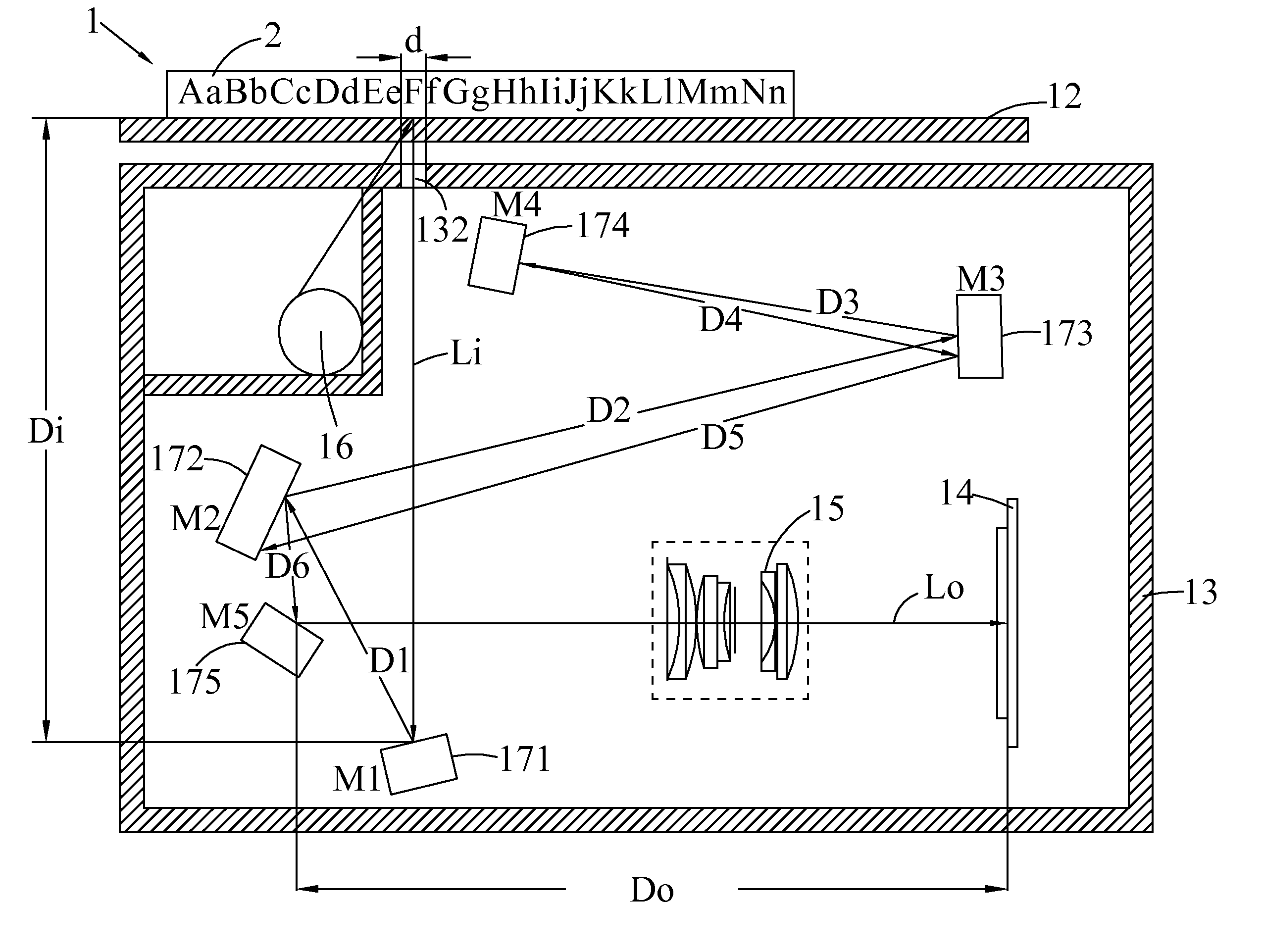
[0024]With reference to FIG. 4 for an image scanning module 1 having five reflecting mirrors for multi-reflection, the image scanning module 1 comprises a light source 16, five reflecting mirrors (M1, M2, M3, M4, M5) 171˜175, a pickup lens 15, an image sensor 14 and a frame 13. After the light source 16 emits a light, the light passes through the cover glass 12 and is projected onto a scanning document 2. The scanning document 2 reflects the light to form a reflected light. After the reflected light passes through the cover glass 12 to form an image beam Li 21 incident at the image scanning module 1. After the image beam Li 21 is incident at a first reflecting mirror (M1)171 to give a first reflection, the reflected image beam is incident at a second reflecting mirror (M2)172 to give a second reflection. The reflected image beam is incident at the third reflecting mirror (M3)173 to give a third reflection, and then reflecting at a fourth reflecting mirror (M4)174 to give a fourth reflection, and then reflecting at the third reflecting mirror (M3)173 to give a fifth reflection, and then reflecting at the second reflecting mirror (M2)172 to give a sixth reflection, and then reflecting at the fifth reflecting mirror (M5)175 to give a seventh reflection, and finally an image beam Lo incident at the pickup lens 15 is formed. The optical path is Li (Obj, document)→M1→M2→M3→M4→M3→M2→M5→Lo (Img, image sensor); wherein the second reflecting mirror (M2)172 and third reflecting mirror (M3)173 have multi-reflection, and each of the second and third mirror undergoes a reflection twice.
[0025]The present invention provides an image scanning module having five reflecting mirrors for multi-reflection as shown in FIG. 4, and the image scanning module comprises at least one light source, five reflecting mirrors, a pickup lens, an image sensor and a frame. On the X-Z plane, one half of the total distance between the reflecting mirrors and the total tracking length (TTL) satisfy the condition of:
0.7 ≤ D refl 2 ( TTL - D refl ) ≤ 1.0 ;
[0026]where, TTL is the total tracking length TTL=Di+D1+D2+D3+D4+D5+D6 +DO; Drefl is the total distance between the reflecting mirrors along the optical path, and Drefl=D1+D2+D3+D4+D5+D6 as shown in FIG. 4; and the angle between the mirrors satisfies the condition of:
- π ( p + 1 ) ≤ ∑ i = 1 p α i - π 2 ( p + 1 ) ≤ π ( p + 1 ) ;
[0027]where αi is an inclined angle (rad.) between the normal line of a reflecting plane of an ith reflecting mirror on the optical path and the +Z-axis, and the symbols are illustrated in FIG. 5, and p is the total number of reflection times along the optical path, and p=7 as shown in FIG. 4,
∑ i = 1 p α i - π 2 ( p + 1 ) = ( α 1 + α 2 + α 3 + α 4 + α 3 + α 2 + α 5 ) - π 2 ( 7 + 1 ) ; ( 3 )
[0028]In a positional relation of the reflecting mirrors, the coordinates (MkX, MkZ) of a reflecting point, an angle of a reflecting mirror and an angle of light incident at a reflecting mirror light of the previous reflecting mirror are determined by:
M(k+1)X=MkX−Dk sin(180±(2αk+βk)) M(k+1)Z=MkZ−Dk Cos(180±(2αk+βk)); (4)
[0029]where (MkX, MkZ) is the (X,Z) coordinates of a reflecting point of the kth reflecting mirror, and βi is an inclined angle(rad.) between the image beam incident at the kth reflecting mirror and the +Z-axis, as illustrated in FIG. 5.
[0030]To effectively reduce the volume of the frame while maintaining the total tracking length unchanged, the reflecting mirror of the present invention undergo multi-reflection, wherein the reflecting mirror (M2) 172 reflects the image beam twice, and the reflecting mirror (M3) 173 reflects the image beam twice. In the prior art, the same reflecting mirror undergoing multi-reflection will produce a serious overlapped light beam to give a ghost image phenomenon, and it is necessary to dispose or adjust the width and the angle of the reflecting mirrors appropriately to reduce the overlapped light beam. However, the image scanning module having five reflecting mirrors in accordance with the present invention adopts a longer tracking length of the optical path M2→M3 and M3→M2 of a reflecting mirror having multi-reflection, and a shorter tracking length at the reflecting point of the reflecting mirror having multi-reflection, so as to reduce the overlapped light beam effectively.
[0031]In FIG. 6, after the light source 16 emits a light, the light passes through the cover glass 12 and is projected onto a scanning document 2. The light projected onto the scanning document 2 is reflected and passed through the cover glass 12 to form an image beam Li 21 incident at the image scanning module 1. The image beam Li′ passing through an aperture 132 on the frame is an overlapped light beam, and the image beam Li′ is reflected from the first reflecting mirror (M1)171 for a first reflection, and then the reflected light of the image beam Li produces a reflection with a different angle, and then is reflected from the second reflecting mirror (M2) 172 and the third reflecting mirror (M3) 173. Since the angle of reflection exceeds the reflection range of the fourth reflecting mirror (M4) 174, therefore the image beam Li′ is eliminated. If the overlapped light beam Li′ passes through the aperture 132 and enters into the image module, the overlapped light beam Li′ will be affected by the angle of incidence of the light on each reflecting mirror and he angle of the reflecting mirror plane, such that the factor of overlapped light beam (FOL) and the diameter d of the aperture are related to the angle of the reflecting mirror plane and the width of the reflecting mirror plane. On the reflecting mirror (M3) 173, the factor of overlapped light beam (FOL) is eliminated. A good effect of eliminating the overlapped light may be obtained, if the condition of Equation (5) may be achieved:
FOL = sin ( α 1 ) · sin ( α 2 ) · sin ( α 3 ) d · λ 3 ≤ 1 2 ; ( 5 ) λ 3 = ( M 3 X - M 5 X ) 2 + ( M 3 Z - M 5 Z ) 2 ; ( 6 )
[0032]wherein, λ3 is the minimum width of the reflecting mirror (M3) 173, which may be represented by the coordinates of the reflecting point. In other words, (M3X, M3Z) and (M5X, M5Z) on the X-Z plane are coordinates of the reflecting points of twice reflection of the image beam occurred at M3; and FOL is a factor of overlapped light beam (FOL), and d is the diameter of the aperture.
[0033]The penta-mirror multi-reflection scanning module in accordance with the present invention changes the direction and path of the image of the scanning document through the five reflecting mirrors and increases the total tracking length; such that the distance between the reflecting mirrors and the total tracking length (TTL) satisfy Equation (1), and the sum of inclined angles between the normal line of a reflecting plane of each reflecting mirror and the +Z-axis satisfy Equation (2). If the total tracking length is changed, it is necessary to adjust the distance between the reflecting mirrors only. In addition, the angle and the distance of the five reflecting mirrors are arranged on the reflecting mirror (M3) 173 that satisfy Equation (5) to prevent the overlapped light beam from entering into the pickup lens to reduce the ghost image phenomenon.
[0034]In a first preferred embodiment, an image scanning module of A4 size is provided.
[0035]With reference to FIG. 4 for an image scanning module 1 having five reflecting mirrors in accordance with a preferred embodiment of the present invention, the image scanning module 1 comprises a cold cathode fluorescent lamp light source 16, five reflecting mirrors M1(171), M2(172), M3(173), M4(174) and M5(175), a pickup lens 15, an image sensor 14 and a frame 13, and an image scanning module of A4 size is used.
[0036]After the light source 16 emits a light, and the light passes through the cover glass 12 and is projected at the scanning document 2 (Obj), an image beam Li incident at the image scanning module 1 is produced. After the image beam Li is reflected from the reflecting mirror M1 and projected to the reflecting mirror M2, the image beam Li is reflected by the reflecting mirror M2 and projected to the reflecting mirror M3, and then reflected by the reflecting mirror M3 and projected to the reflecting mirror M4, and then reflected by the reflecting mirror M4 and projected to the reflecting mirror M3, and then reflected from the reflecting mirror M3 and projected to the reflecting mirror M2, and reflected from the reflecting mirror M2 and projected to the reflecting mirror M5, and then reflected from the reflecting mirror M5 to form an image beam Lo. The image beam Lo is focused by the pickup lens 15 to form an image (Img) at the image sensor 14. The frame 13 is provided for disposing each component of the image scanning module 1. The optical path is Li(Obj)→M1→M2→M3→M4→M3→M2→M5→Lo(Img), and αi is an inclined angle between the normal line of a reflecting plane of each reflecting mirror Mi and the +Z-axis, and the coordinates of a reflecting point of the reflecting mirror Mi on the X-Z plane at that time are (MiX, MiZ).
TABLE 1 Optical Parameters of the First Preferred Embodiment Surface α i (°Deg.) Di (mm) (MiX, MiZ) Obj 0 (0, 0) M1 171.2 70.60 (0, 70.60) M2 59.2 34.96 (−10.51, 37.26) M3 87.2 61.15 (49.65, 26.29) M4 72.3 17.14 (33.21, 21.46) M3 87.2 17.45 (49.59, 27.46) M2 59.4 65.80 (−14.24, 43.45) M5 142.5 21.04 (−9.24, 63.89) Img 70.60 (57.832, 63.89)
[0037]In this preferred embodiment, the total number of reflection times p=7, and the total distance between the reflecting mirrors and the total tracking length (TTL) satisfy Equation (1), and the sum of angles of each reflecting mirror along the optical path satisfies Equation (2), and the diameter of an aperture 132 on the frame 13 where the multi-reflection occur at M2 and M3, frame 13 is d=5 mm, and the reflecting mirror (M3) 173 satisfies Equation (5), in order to eliminate the overlapped light and stop the ghost image phenomenon effectively.
TTL = D i + D 1 + D 2 + D 3 + D 4 + D 5 + D 6 + D O = 355.22 mm D refl 2 ( TTL - D refl ) = 0.7901 ∑ i = 1 7 α i - π 2 ( 7 + 1 ) = 0.022 · π ≤ π ( 7 + 1 ) FOL = 0.0307
[0038]In a second preferred embodiment, an image scanning module of A3 size is provided.
[0039]With reference to FIG. 7 for an image scanning module 1 having five reflecting mirrors in accordance with a preferred embodiment of the present invention, the image scanning module 1 comprises two cold cathode fluorescent lamp light sources 16a, 16b, five reflecting mirrors M1(171), M2(172), M3(173), M4(174) and M5(175), a pickup lens 15, an sensor 14 and a frame 13, and the A3 sized image scanning module is used in this preferred embodiment. The total tracking length (TTL) of the A3 sized image scanning module is longer than the total tracking length of the A4 sized image scanning module, and the TTL of this preferred embodiment is 492.98 mm. After the distance between the reflecting mirrors is adjusted without changing the angle of each reflecting mirror, the total tracking length of the A4 sized image scanning module is adjusted to the total tracking length of the A3 sized image scanning module.
[0040]The optical path of this preferred embodiment is the same as that of the first preferred embodiment, which is Li(Obj)→M1→M2→M3→M4→M3→M2→M5→Lo(Img), and αi is an inclined angle between the normal line of a reflecting plane of each reflecting mirror Mi and the +Z-axis, and the coordinates of a reflecting point of the reflecting mirror Mi on the X-Z plane at that time are (MiX, MiZ) as shown in Table 2.
TABLE 2 Optical Parameters of the Second Preferred Embodiment Surface α i (°Deg.) Di (mm) (MiX, MiZ) Obj 0 (0, 0) M1 171.2 70.60 (0, 70.60) M2 59.2 27.00 (−8.09, 44.93) M3 87.2 93.37 (83.73, 28.17) M4 72.3 43.80 (41.70, 15.82) M3 87.2 44.59 (83.57, 31.15) M2 59.4 101.08 (−14.63, 55.75) M5 142.5 8.37 (−12.64, 63.89) Img 104.21 (91.5655, 63.89)
[0041]In this preferred embodiment, the total number of reflection times p=7, and the total distance between the reflecting mirrors and the total tracking length (TTL) satisfy Equation (1), and the sum of angles of each reflecting mirror along the optical path satisfies Equation (2), and the diameter of an aperture 132 on the frame 13 where the multi-reflection occur at M2 and M3 is d=5 mm, and the reflecting mirror (M3) 173 satisfies Equation (5), in order to eliminate the overlapped light and stop the ghost image phenomenon effectively.
TTL = D i + D 1 + D 2 + D 3 + D 4 + D 5 + D 6 + D O = 492.98 mm D refl 2 ( TTL - D refl ) = 0.9101 ∑ i = 1 7 α i - π 2 ( 7 + 1 ) = 0.022 · π ≤ π ( 7 + 1 ) FOL = 0.0783
[0042]Compared with the first preferred embodiment, this preferred embodiment simply adjusts the distance of the reflecting mirrors without the need of adjusting the angle of the reflecting mirror in order to adjust the TTL of the first preferred embodiment from 355.22 mm to 492.98 mm to broaden the scope of applicability.
[0043]In a third preferred embodiment, an image scanning module of A4 size is provided.
[0044]With reference to FIG. 8 for an image scanning module 1 having five reflecting mirrors in accordance with a preferred embodiment of the present invention, the image scanning module 1 comprises a cold cathode fluorescent lamp light source 16, five reflecting mirrors M1(171), M2(172), M3(173), M4(174) and M5(175), a pickup lens 15, an image se and a frame 13, wherein an A4 sized image scanning module is used in this preferred embodiment.
[0045]After the light source 16 emits a light, and the light passes through the cover glass 12 and is projected onto scanning document 2(Obj), an image beam Li incident at the image scanning module 1 is produced.
[0046]The optical path of this preferred embodiment is the same as those of the first and second preferred embodiments, which is Li(Obj)→M1→M2→M3→M4→M3→M2→M5→Lo(Img), and αi is an inclined angle between the normal line of a reflecting plane of each reflecting mirror Mi and the +Z-axis, and the coordinates of a reflecting point of the reflecting mirror Mi on the X-Z plane at that time are (MiX, MiZ) as shown in Table 3.
TABLE 3 Optical Parameters of the Third Preferred Embodiment Surface α i (°Deg.) Di (mm) (MiX, MiZ) Obj 0 (0, 0) M1 165.7 58.10 (0, 58.10) M2 65.8 23.88 (−11.04, 36.85) M3 87.2 60.71 (47.89, 23.05) M4 78.7 36.40 (12.32, 16.97) M3 87.9 36.08 (47.93, 24.52) M2 65.6 63.52 (−13.26, 41.52) M5 121.3 10.26 (−8.84, 50.72) Img 66.26 (57.42, 50.72)
[0047]In this preferred embodiment, the total number of reflection times p=7, and the total distance between the reflecting mirrors and the total tracking length (TTL) satisfy Equation (1), and the sum of angles of each reflecting mirror along the optical path satisfies Equation (2), and the diameter of an aperture 132 on the frame 13 where the multi-reflection occur at M2 and M3 is d=5 mm, and the reflecting mirror (M3) 173 satisfies Equation (5), in order to eliminate the overlapped light and stop the ghost image phenomenon effectively.
TTL = D i + D 1 + D 2 + D 3 + D 4 + D 5 + D 6 + D O = 355.22 mm D refl 2 ( TTL - D refl ) = 0.9281 - π ( 7 + 1 ) ≤ ∑ i = 1 7 α i - π 2 ( 7 + 1 ) = 0.0162 · π FOL = 0.2275
In a fourth preferred embodiment, an image scanning module of A3 size is provided.
[0048]With reference to FIG. 8 for an image scanning module 1 having five reflecting mirrors in accordance with a preferred embodiment of the present invention, the image scanning module 1 comprises a cold cathode fluorescent lamp light source 16, five reflecting mirrors M1(171), M2(172), M3(173), M4(174) and M5(175), a pickup lens 15, an image sensor 14 and a frame 13, wherein an A3 sized image scanning module is used in this preferred embodiment, and the TTL=492.98 mm, and the distance between the reflecting mirrors of the image scanning module of the third preferred embodiment is adjusted without changing the angle of each reflecting mirror, such that the TTL of the A4 sized image scanning module is adjusted to the TTL of the A3 sized image scanning module.
[0049]The optical path of this preferred embodiment is the same as that of the third preferred embodiment, which is Li(Obj)→M1→M2→M3→M4→M3→M2→M5→Lo(Img), and αi is an inclined angle between the normal line of a reflecting plane of each reflecting mirror Mi and the +Z-axis, and the coordinates of a reflecting point of the reflecting mirror Mi on the X-Z plane at that time are (MiX, MiZ) as shown in Table 4.
TABLE 4 Optical Parameters of the Fourth Preferred Embodiment Surface α i (°Deg.) Di (mm) (MiX, MiZ) Obj 0 (0, 0) M1 166.1 58.1 (0, 58.1) M2 65.9 36.45 (−17, 25.86) M3 88.2 78.45 (59.12, 6.88) M4 78.8 21.56 (37.91, 2.99) M3 88.2 20.65 (58.11, 7.28) M2 65.9 83.34 (−22.16, 29.69) M5 122.4 24.56 (−11.31, 51.73) Img 169.86 (158.55, 51.73)
[0050]In this preferred embodiment, the total number of reflection times p=7, and the total distance between the reflecting mirrors and the total tracking length (TTL) satisfy Equation (1), and the sum of angles of each reflecting mirror along the optical path satisfies Equation (2), and the diameter of an aperture 132 on the frame 13 where the multi-reflection occur at M2 and M3 is d=5 mm, and the reflecting mirror (M3) 173 satisfies Equation (5), in order to eliminate the overlapped light and stop the ghost image phenomenon effectively.
TTL = D i + D 1 + D 2 + D 3 + D 4 + D 5 + D 6 + D O = 492.98 mm D refl 2 ( TTL - D refl ) = 0.5751 - π ( 7 + 1 ) ≤ ∑ i = 1 7 α i - π 2 ( 7 + 1 ) = - 0.0162 · π FOL = 0.0475
[0051]Compared with the third preferred embodiment, this preferred embodiment simply adjusts the distance of the whole set of reflecting mirrors without the need of adjusting the angle of the reflecting mirror in order to adjust the TTL of the first preferred embodiment from 355.22 mm to 492.98 mm to broaden the scope of applicability.
[0052]In a fifth preferred embodiment, an image scanning module of small A3 size is provided.
[0053]With reference to FIG. 9 for an image scanning module 1 having five reflecting mirrors in accordance with a preferred embodiment of the present invention, the image scanning module 1 comprises a cold cathode fluorescent lamp light source 16, five reflecting mirrors M1(171), M2(172), M3(173), M4(174) and M5(175), a pickup lens 15, an image se and a frame 13, wherein an A3 sized image scanning module is used in this preferred embodiment similar to the fourth preferred embodiment, and the TTL=492.98 mm, and the distance between the reflecting mirrors of the image scanning module of the fourth preferred embodiment is adjusted without changing the angle of each reflecting mirror, such that the volume of the A4 sized image scanning module may be reduced.
[0054]The optical path of this preferred embodiment is the same as that of the third preferred embodiment, which is Li(Obj)→M1→M2→M3→M4→M3→M2→M5→Lo(Img), and αi is an inclined angle between the normal line of a reflecting plane of each reflecting mirror Mi and the +Z-axis, and (MiX, MiZ) are coordinates of a reflecting point of a reflecting mirror Mi on the X-Z plane as shown in Table 5:
TABLE 5 Optical Parameters of the Fifth Preferred Embodiment Surface α i (°Deg.) Di (mm) (MiX, MiZ) Obj 0 (0, 0) M1 166.1 76.61 (0, 76.61) M2 65.9 34.15 (−15.99, 46.44) M3 88.2 84.89 (73.15, 23.95) M4 78.8 55.39 (12.55, 17.70) M3 88.2 54.9 (65.70, 29.20) M2 65.9 88.93 (−18.90, 53.00) M5 122.4 9.67 (−14.80, 61.70) Img 88.46 (69.56, 61.70)
[0055]In this preferred embodiment, the total number of reflection times p=7, and the total distance between the reflecting mirrors and the total tracking length (TTL) satisfy Equation (1), and the sum of angles of each reflecting mirror along the optical path satisfies Equation (2), and the diameter of an aperture 132 on the frame 13 where the multi-reflection occur at M2 and M3 is d=5 mm, and the reflecting mirror (M3) 173 satisfies Equation (5), in order to eliminate the overlapped light and stop the ghost image phenomenon effectively.
TTL = D i + D 1 + D 2 + D 3 + D 4 + D 5 + D 6 + D O = 492.98 mm D refl 2 ( TTL - D refl ) = 0.9933 - π ( 7 + 1 ) ≤ ∑ i = 1 7 α i - π 2 ( 7 + 1 ) = - 0.0162 · π FOL = 0.3711
[0056]Compared with the fourth preferred embodiment, the frame of this preferred embodiment has a larger thickness and a smaller length, such that users simply need to adjust the distance between the reflecting mirrors to reduce the volume of the image scanner and meet the requirements for a compact design.
[0057]In summation of the description above, the penta-mirror multi-reflection scanning module in accordance with the present invention uses at least two of the five reflecting mirrors for multi-reflection to constitute an optical path to increase the length of the optical path and the depth of field, and substantially reduce or eliminate the overlapped light produced by the multi-reflection of the reflecting mirrors, so as to reduce the ghost image phenomenon.
[0058]The penta-mirror multi-reflection scanning module in accordance with the present invention simply adjusts the distance of the reflecting mirrors during the manufacturing and assembling processes without the need of adjusting the angle, so that the image scanning module may be used for the A4/A3 sizes and different effective focal lengths of the pickup lenses to provide a broader scope of applicability.
[0059]While the invention has been described by means of specific embodiments, numerous modifications and variations could be made thereto by those skilled in the art without departing from the scope and spirit of the invention set forth in the claims.