
Air conditioner for vehicle

a technology for air conditioners and vehicles, applied in the direction of indirect heat exchangers, refrigeration components, light and heating apparatuses, etc., can solve the problems of reducing the operation efficiency of the engine, inability to obtain sufficient heat, etc., to achieve the effect of reducing the energy loss due to the heat radiation in the engine, achieving sufficient heating capacity, and achieving the effect of heating capacity

Inactive Publication Date: 2010-11-11
DENSO CORP +1
View PDF4 Cites 92 Cited by
  • Summary
  • Abstract
  • Description
  • Claims
  • Application Information

AI Technical Summary

Benefits of technology

[0006]In view of the above points, it is an object of the present invention to provide an air conditioner for a vehicle, which can save force used for a heater.
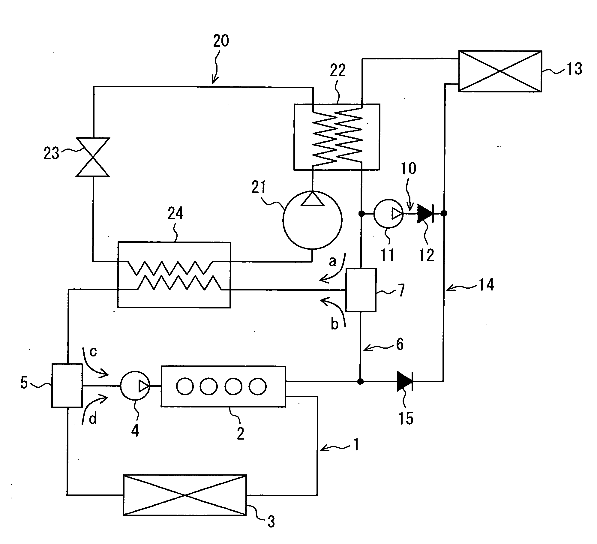
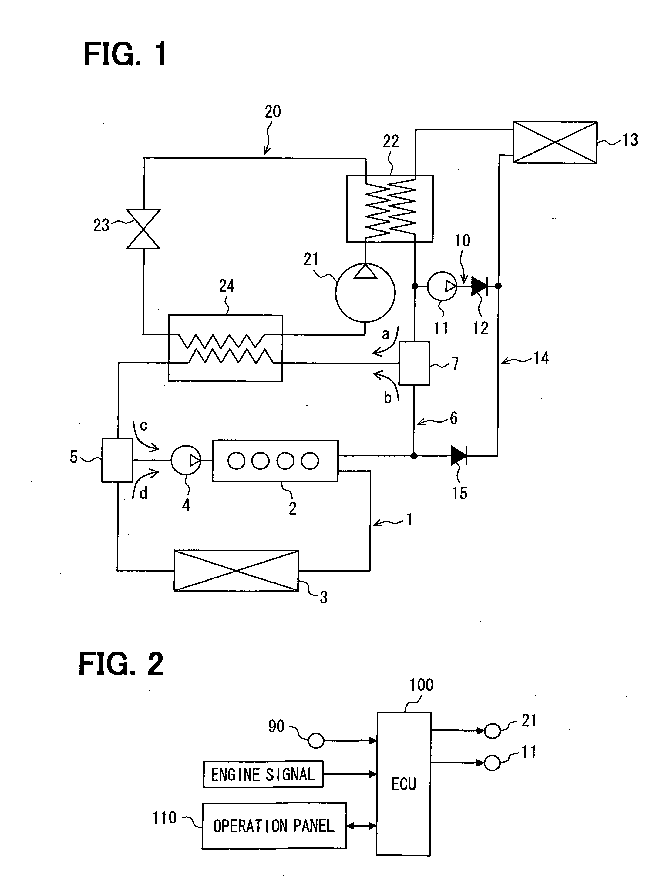
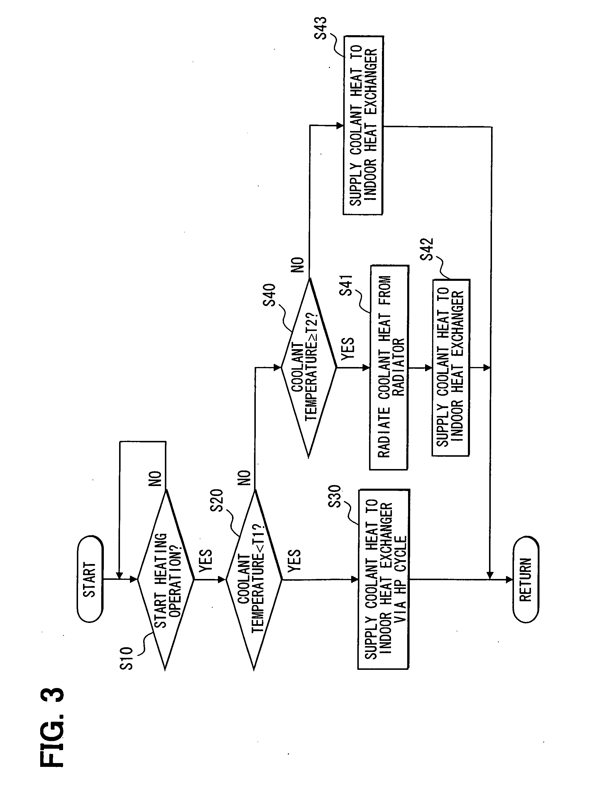
[0008]According to the configuration, when the sufficient heating capacity is obtained from the coolant in the heating operation, the coolant flows in the indoor heat exchanger to heat air to be supplied to vehicle compartment. In contrast, when the sufficient heating capacity is not obtained from the coolant, the coolant flows through the first water-refrigerant heat exchanger and the heat of the coolant is absorbed by the refrigerant circulating in the heat pump cycle by the heat pump so that the heat that has been absorbed by the refrigerant is radiated in the indoor heat exchanger to heat the air. Further, heat of the refrigerant is radiated in the high-pressure side heat exchanger of the heat pump cycle so that the air is heated. The heating operation that uses the heat of the coolant for the heater can be obtained without increasing the coolant temperature as described in the conventional technique. Thus, the coolant temperature can be maintained low and energy loss due to the heat radiation in the engine can be decreased and further, exhaust heat from the engine is transferred efficiently to the refrigerant by the heat pump so that the heating capacity can be obtained. Therefore, the force for operating the heater can be saved, and the energy efficiency of the, entire vehicle and the fuel consumption can be improved.

Problems solved by technology

However, in the conventional technique, the sufficient feeling of heat cannot be obtained when the coolant temperature is low at the starting of the engine operation, for example.
Further, in order to improve the heating capacity by increasing the amount of heat supplied from the heater core, the engine should be excessively operated with respect to an operation state of the vehicle, resulting in decreasing the operation efficiency of the engine.

Method used


Image

  • Air conditioner for vehicle
  • Air conditioner for vehicle
  • Air conditioner for vehicle

Examples


first embodiment

[0022]A vehicle air conditioner of a first embodiment of the present invention will be described with reference to FIGS. 1 to 3.

[0023]As shown in FIG. 1, the vehicle air conditioner is a circuit to which an engine 2 for driving a vehicle is connected, and includes a coolant circuit, in which a coolant for cooling the engine 2 circulates, and a vapor-compression type heat pump cycle 20 that conditions air in a vehicle compartment by controlling a state of a circulating refrigerant. Further, the vehicle air conditioner is a device that causes heat of at least one of the coolant and the refrigerant to be used for a heater in the vehicle compartment. The heat pump cycle 20 includes a compressor 21, a second water-refrigerant heat exchanger 22 as a high-pressure side heat exchanger, an expansion valve 23 and a first water-refrigerant heat exchanger 24 that exchanges heat between the coolant and the refrigerant, and configures a refrigerant circuit in which these components are circularly...

second embodiment

[0052]In a second embodiment, another example of the vehicle air conditioner of the first embodiment will be described with reference to FIG. 4. A component in FIG. 4, which is designated by the same reference numeral with the component in FIG. 1, is the same component with that of the first embodiment, and has the similar effect described In the first embodiment.

[0053]As shown in FIG. 4, a heat pump cycle 20A of a vehicle air conditioner of the present embodiment differs from the-heat pump cycle 20 of the first embodiment in that an outdoor heat exchanger 25 is arranged at a discharge side of the expansion valve 23 as the first decompression device. The outdoor heat exchanger 25 is a heat exchanger configured such that a refrigerant circulating in the heat pump cycle 20A flows through the inside thereof and outdoor air to be heat-exchanged with the refrigerant flows through the outside thereof. Further, a blower fan 26 for blowing the outdoor air is arranged adjacent to the outdoor...

third embodiment

[0061]In a third embodiment, another example of the vehicle air conditioner of the first embodiment will be described with reference to FIGS. 5 and 6. A component or a step in FIGS. 5 and 6, which is designated by the same reference numeral with the component or the step in FIGS. 1 and 3, is the same component or the step with that of the first embodiment, and has the similar effect described in the first embodiment.

[0062]As shown in FIG. 5, a heat pump cycle 20B of a vehicle air conditioner of the present embodiment differs from the heat pump cycle 20 of the first embodiment in the following points. The heat pump cycle 20B has the refrigerant passage that is branched into a first refrigerant passage and a second refrigerant passage 30 at a discharge side of the second water-refrigerant heat exchanger 22. In the first refrigerant passage, the expansion valve 23 and the first water-refrigerant heat exchanger 24 are arranged in this order in the downstream direction. In the second ref...


PUM


Abstract

In an air conditioner for a vehicle, in a heating operation for heating a vehicle compartment, when heating capacity is obtained by flowing a coolant through an inside of an indoor heat exchanger, the coolant flows directly in the inside of the indoor heat exchanger to heat air to be supplied to the vehicle compartment. In contrast, when the heating capacity is not obtained by flowing the coolant through the inside of the indoor heat exchanger, the coolant flows through a first water-refrigerant heat exchanger and a refrigerant in a heat pump cycle circulates so that heat of the coolant is absorbed by the refrigerant in the first water-refrigerant heat exchanger, and the air is heated in the indoor heat exchanger by using heat of the refrigerant that has absorbed the heat of the coolant.

Description

CROSS REFERENCE TO RELATED APPLICATION[0001]The present application is based on Japanese Patent Application No. 2009-112986 filed on May 7, 2009, the disclosure of which is incorporated herein by reference.FIELD OF THE INVENTION[0002]The present invention relates to an air conditioner for a vehicle (also referred to as a vehicle air conditioner), in which an engine coolant is used as a heat source for a heater.BACKGROUND OF THE INVENTION[0003]For example, according to a conventional vehicle air conditioner described in JP-A-11-170848, in a heating operation in a vehicle compartment, a coolant after cooling an engine, which is introduced to a heater core, is used as a heat source for a heater and air heated in a sub-condenser with the use of a high temperature refrigerant by a heat pump is used as a heat source for a heater.[0004]In the conventional technique, when the engine is operated, air in a duct of the air conditioner is heated by the coolant introduced to the heater core so t...

Claims


Application Information

Patent Timeline
IPC IPC(8): F25B27/00B60H3/00F25B41/00F25B13/00F25B43/00F28D1/00
CPCB60H1/00885B60H1/20F25B2339/047B60H2001/00949F25B25/005B60H2001/00928B60H1/32284
Inventor KAWASE, YASUHIROOZAKI, YUKIKATSUINAGAKI, MITSUO
Owner DENSO CORP
Learn More