Apparatus and Method for Condensing Contaminants for a Cryogenic System

a technology of apparatus and method, applied in lighting and heating apparatus, water/sludge/sewage treatment, crystallization separation, etc., can solve the problems of background art not teaching or suggesting suitable, simple, efficient and inexpensive apparatus or methods

Inactive Publication Date: 2010-11-11
ICECURE MEDICAL
View PDF104 Cites 9 Cited by
  • Summary
  • Abstract
  • Description
  • Claims
  • Application Information

AI Technical Summary

Benefits of technology

[0011]According to some embodiments, the present invention features a separator unit, for removing readily-condensing contaminants such as water vapors, carbon dioxide and hydrocarbons from the ambient feed air, for example and without limitation, to avoid damage such as clogging in a gas liquefaction system by these frozen readily-condensing contaminants. Preferably, the separator unit is adapted for use in a small scale system.

Problems solved by technology

The background art does not teach or suggest a suitable, simple, efficient and inexpensive apparatus or method for removing contaminants, particularly gaseous contaminants, from a gaseous cryogen before its liquefaction.

Method used


Image

  • Apparatus and Method for Condensing Contaminants for a Cryogenic System
  • Apparatus and Method for Condensing Contaminants for a Cryogenic System
  • Apparatus and Method for Condensing Contaminants for a Cryogenic System

Examples


Embodiment Construction

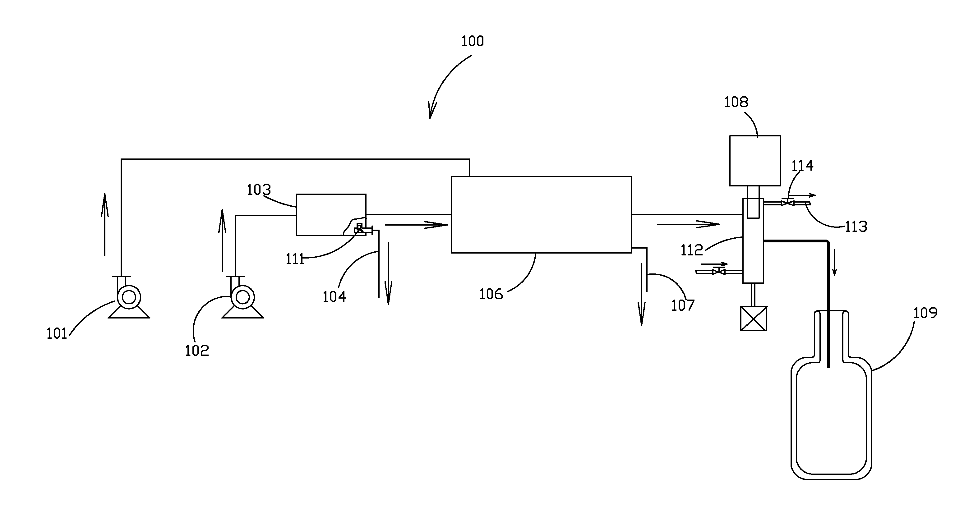
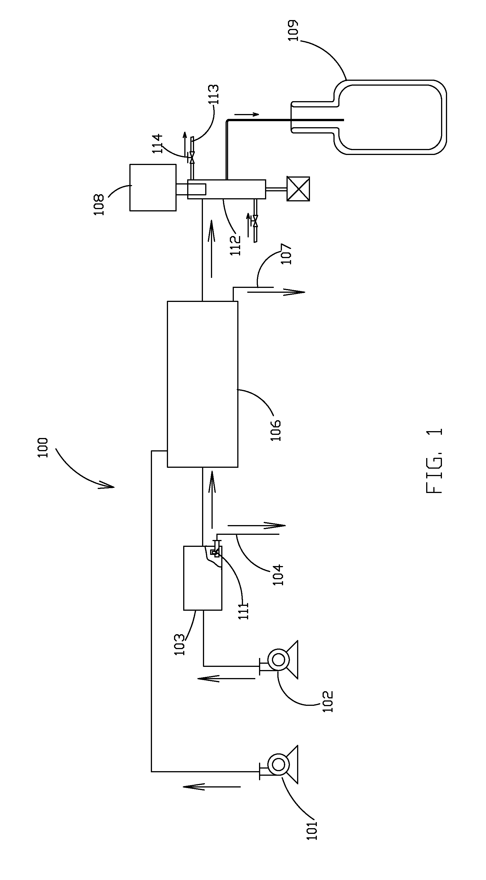
[0028]FIG. 1 shows a block-diagram of an illustrative, general system of gas liquefaction and purification according to at least some embodiments of the present invention.

[0029]A system 100 of gas liquefaction and purification, comprises a main air blower 102 and optionally and preferably an auxiliary air blower 101, operative for blowing-off readily-condensing contaminants.

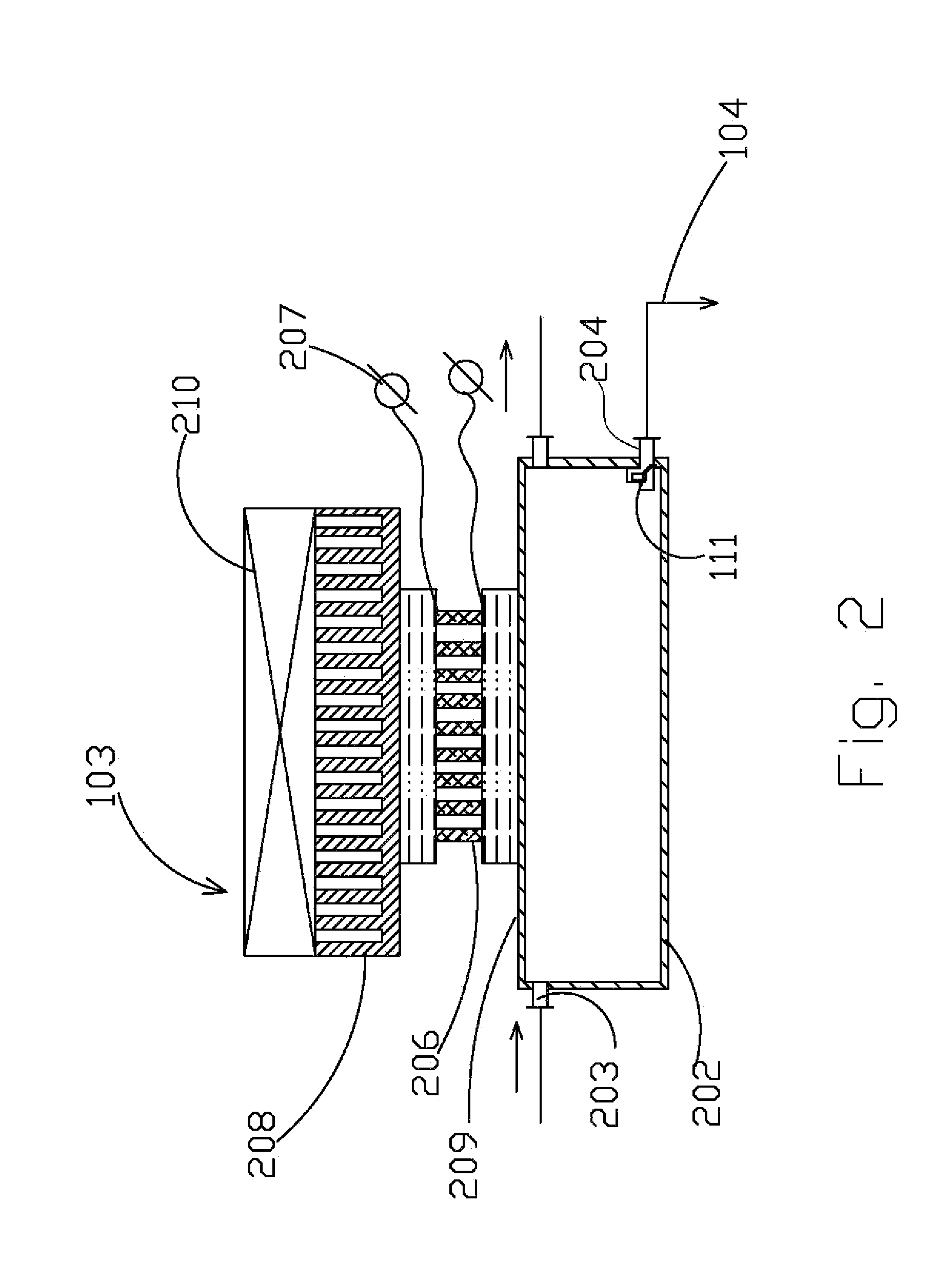
[0030]The gas (air) to be liquefied enters the main air blower 102 and from the main air blower 102 passes through a heat exchanging chamber 103, which removes a significant fraction of water vapor contained in the air through cooling, and which may for example optionally comprise a thermoelectric cooler. The obtained condensate is drained via a condensate tapper 111, which is preferably small or miniature, by a condensate line 104. Condensate tapper 111 is connected to or integrally formed with the heat exchanging chamber 103.

[0031]The gas (air) from heat exchanging chamber 103 is preferably passed through an ab...


PUM

PropertyMeasurementUnit
temperatureaaaaaaaaaa

Abstract

A system for removing contaminants from a gas, preferably through condensation and adsorption, followed by liquefaction of the gas.

Description

[0001]This application claims priority from U.S. Provisional Application No. 61 / 111,355, filed on Nov. 5, 2008, which is hereby incorporated by reference as if fully set forth herein.FIELD OF THE INVENTION[0002]The present invention relates to an apparatus and method for preventing ingress of contaminants into a liquid cryogen, and in particular, such an apparatus and method for removing such contaminants through condensation of gaseous cryogen.BACKGROUND OF THE INVENTION[0003]There is a constantly growing demand for small-scale gas liquefaction systems, which can supply to a consumer liquid air, liquid oxygen or liquid nitrogen in the range of some liters per day.[0004]Such systems can be widely applied in medicine (operation of cryosurgical equipment in medical offices, supply of breathing oxygen to persons requiring oxygen therapy in their homes and so forth), in biological and medical laboratories and in electronics (for example, for cooling infrared detectors).[0005]The process...

Claims


Application Information

Patent Timeline
Patent Type & Authority Applications(United States)
IPC IPC(8): F25J3/00B01D9/00
CPCF25J2290/20F25J1/0276B01D53/265B01D2253/106B01D2253/108F25J2205/20F25J2220/40F25J1/0012F25J1/0015F25J1/0017F25J1/0225F25J3/04278F25J2270/908F25J3/04981B01D53/261
Inventor LEVIN, ALEXANDER
Owner ICECURE MEDICAL
Why Eureka
Try Eureka