Heat exchanger shell assembly and method of assembling

a technology of heat exchanger shell and assembly method, which is applied in the direction of heat exchange apparatus, stationary tubular conduit assembly, metal-working apparatus, etc., can solve the problem of unsuitable positioning of the nozzle, and achieve the effect of lowering heat transfer efficiency and convenient installation

Inactive Publication Date: 2010-11-11
EMBAFFLE
View PDF2 Cites 9 Cited by
  • Summary
  • Abstract
  • Description
  • Claims
  • Application Information

AI Technical Summary

Benefits of technology

[0008]By arranging an inner shell member, it is possible to direct shell side fluid from one shell end to the other, using the intermediate space. The inner shell space, in which the actual heat exchange with a tube bundle is to take place, needs to be sealed against the intermediate space, otherwise shell side fluid could flow along a shortcut route, lowering heat transfer efficiency. A seal member between inner shell member and outer shell is provided for this purpose. Preferably, the seal member is a gravity seal member, wherein sealing force is provided by the gravity force exerted on the seal member by the inner shell member. In particular, the seal member is not connected to at least one of the outer shell and the inner shell member, preferably it is not connected to both the outer shell and the inner shell member. This allows particularly easy installation of the shell arrangement, since the sealing member can be pushed into the intermediate space after the inner shell member is arranged in the outer shell, and sealing is simply accomplished lowering the inner shell so that its weight, suitably together with the weight of the tube bundle, exerts the sealing force for the sealing member. Moreover, by not connecting the inner and outer shells via the seal member, different temperature expansion between the outer shell and inner shell member can be accommodated.

Problems solved by technology

A problem is encountered when the number of shell-side passes is to change between even and uneven, since then one of the nozzles is unsuitably located.

Method used


Image

  • Heat exchanger shell assembly and method of assembling
  • Heat exchanger shell assembly and method of assembling
  • Heat exchanger shell assembly and method of assembling

Examples


Embodiment Construction

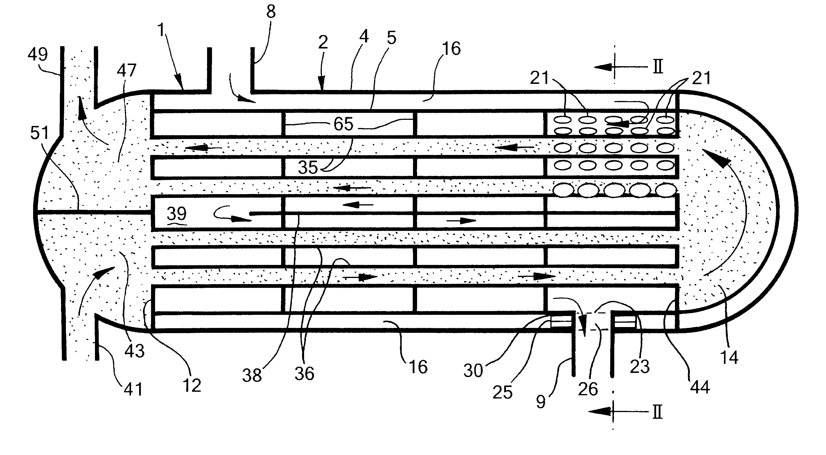
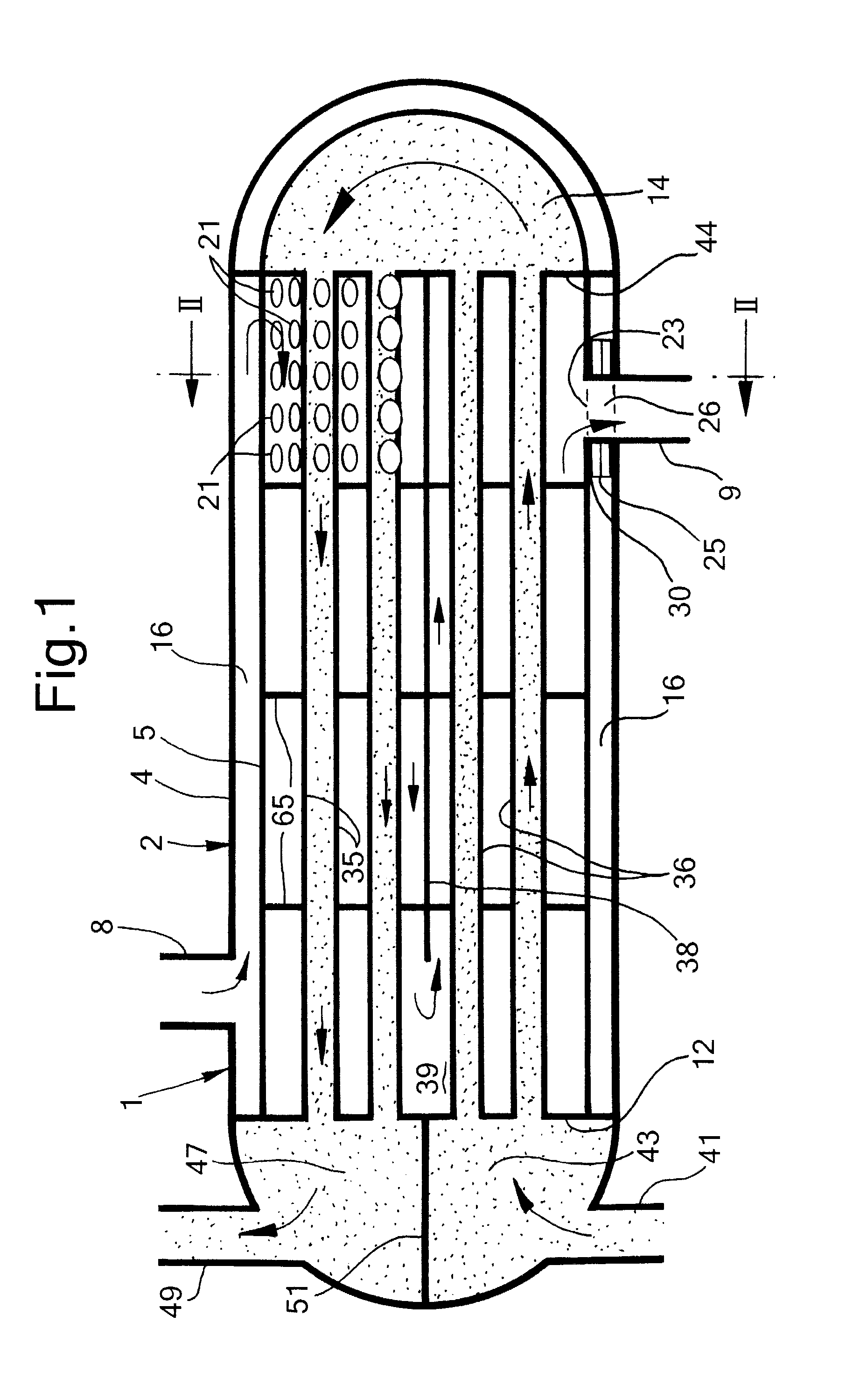
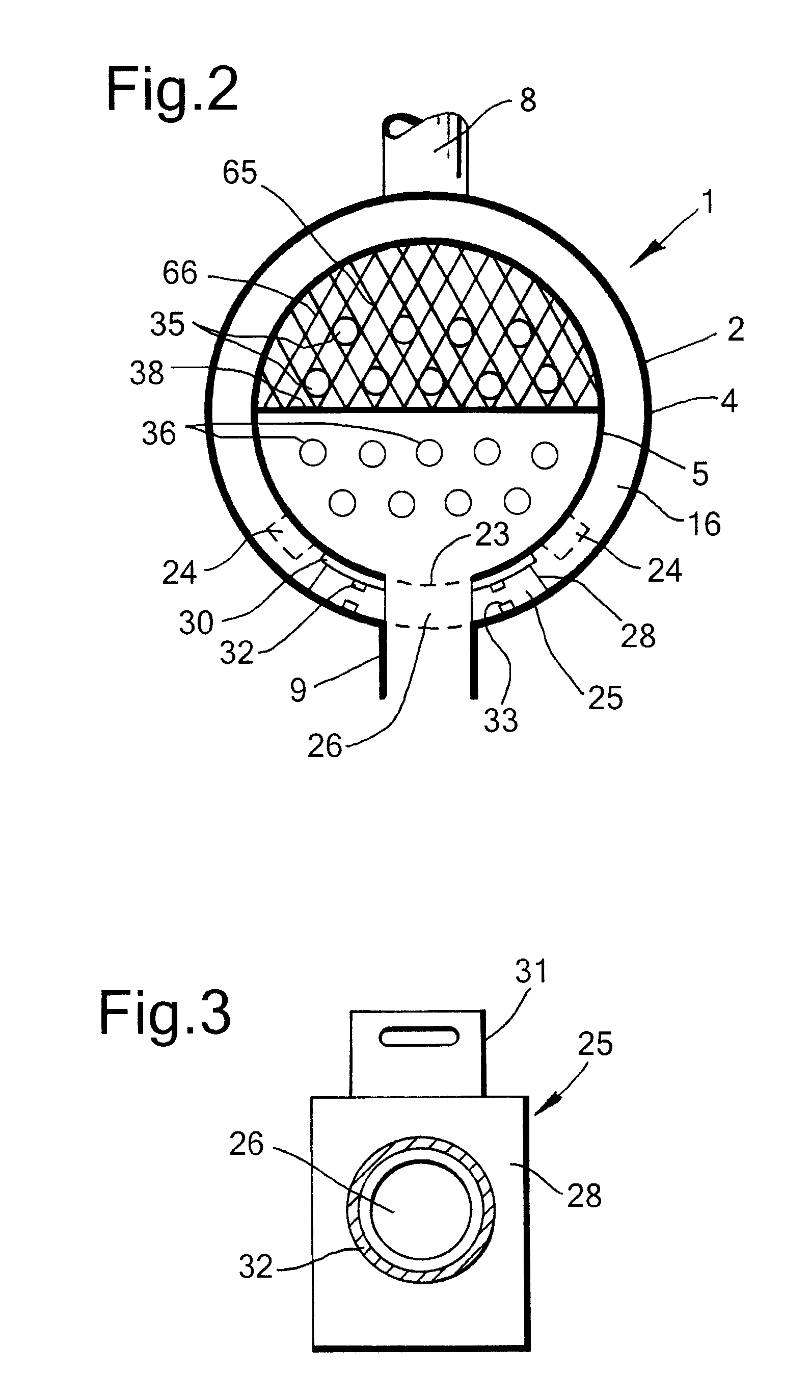
[0023]Reference is made to FIGS. 1-3 showing schematically a heat exchanger 1 including a heat exchanger shell assembly or structure 2 according to the invention. The heat exchanger shell assembly 2 comprises an outer shell 4 and an inner shell member 5. The outer shell 4 has an inlet nozzle 8 (second nozzle) at its upper side and an outlet nozzle 9 (first nozzle) at its lower side. The inner shell member 5 extends cylindrically between a tube sheet 12 and floating head 14, thereby forming an intermediate space 16 with the outer shell. The inner shell member has an inlet opening (second opening) 21 in the form of a plurality of holes around its upper side near the end opposite to the inlet nozzle 8, and an outlet opening 23 (first opening) at its lower side at the same end. For handling during installation, the inner shell member 5 is preferably provided with longitudinal sliding bars 24 on which the inner shell member can be slid into the outer shell 4.

[0024]A seal member 25 is pla...


PUM

PropertyMeasurementUnit
thicknessaaaaaaaaaa
temperaturesaaaaaaaaaa

Abstract

A heat exchanger shell assembly comprising an outer shell having a nozzle at its lower side; an inner shell member within the outer shell and forming an intermediate space with the outer shell, the inner shell member having an opening at its lower side; wherein the arrangement further comprises a seal member arranged to fit in the intermediate space, the seal member providing a sealed passageway for fluid between the opening and the nozzle, and a method of assembling a heat exchanger shell structure, and a method of assembling a heat exchanger shell structure, comprising sliding an inner shell member into an outer shell, to form an intermediate space, arranging the inner shell member in a lifted position in the outer shell; sliding a seal member into the intermediate space; and lowering the inner shell member so that the gravity force exerted on the seal member acts as sealing force.

Description

FIELD OF THE INVENTION[0001]The present invention relates to a heat exchanger shell assembly and a method of assembling a heat exchanger shell structure.BACKGROUND OF THE INVENTION[0002]A shell-and-tube heat exchanger is an indirect heat exchanger. Heat is transferred between a fluid passing through the tubes of a tube bundle (the tube side) extending in a heat exchanger shell, and a fluid passing through the space outside the tubes (the shell side). Details of shell-and-tube heat exchangers can for example be found in Perry's Chemical Engineers' Handbook, 7th edition, 1997, McGraw-Hill Inc., page 11-33 to 11-46.[0003]Shell-and-tube heat exchangers can be distinguished according to the number of passes for fluid in the shell side and in the tube side. In each pass, the respective fluid flows substantially along the entire length of the heat exchanger, which is typically horizontally elongated. In multiple shell passes, the fluid flow meanders a plurality of times back and forth the ...

Claims


Application Information

Patent Timeline
Patent Type & Authority Applications(United States)
IPC IPC(8): F28D7/16F28F9/22B21D53/06
CPCF28D7/1607F28F9/22Y10T29/49361F28F2230/00F28F2009/224F28F9/26F28D7/00F28D7/16
Inventor MULDER, DOMINICUS FREDERICUS
Owner EMBAFFLE
Why Eureka
Try Eureka