Method for aligning pixilated micro-grid polarizer to an image sensor

Inactive Publication Date: 2010-11-11
EMERGENTVIEWS
View PDF4 Cites 20 Cited by
  • Summary
  • Abstract
  • Description
  • Claims
  • Application Information

AI Technical Summary

Benefits of technology

[0008]To minimize the separation distance between the imaging sensor and the micro-grid polarizer the imaging sensor may be illuminated (through the micro-grid polarizer) using light that is polarized parallel to one of a plurality of angles of pixel

Problems solved by technology

While gross alignments therebetween can be made with expensive microscopy equipment and using fiducial marks or other complementary alignment aids embossed on

Method used


Image

  • Method for aligning pixilated micro-grid polarizer to an image sensor
  • Method for aligning pixilated micro-grid polarizer to an image sensor
  • Method for aligning pixilated micro-grid polarizer to an image sensor

Examples


Embodiment Construction

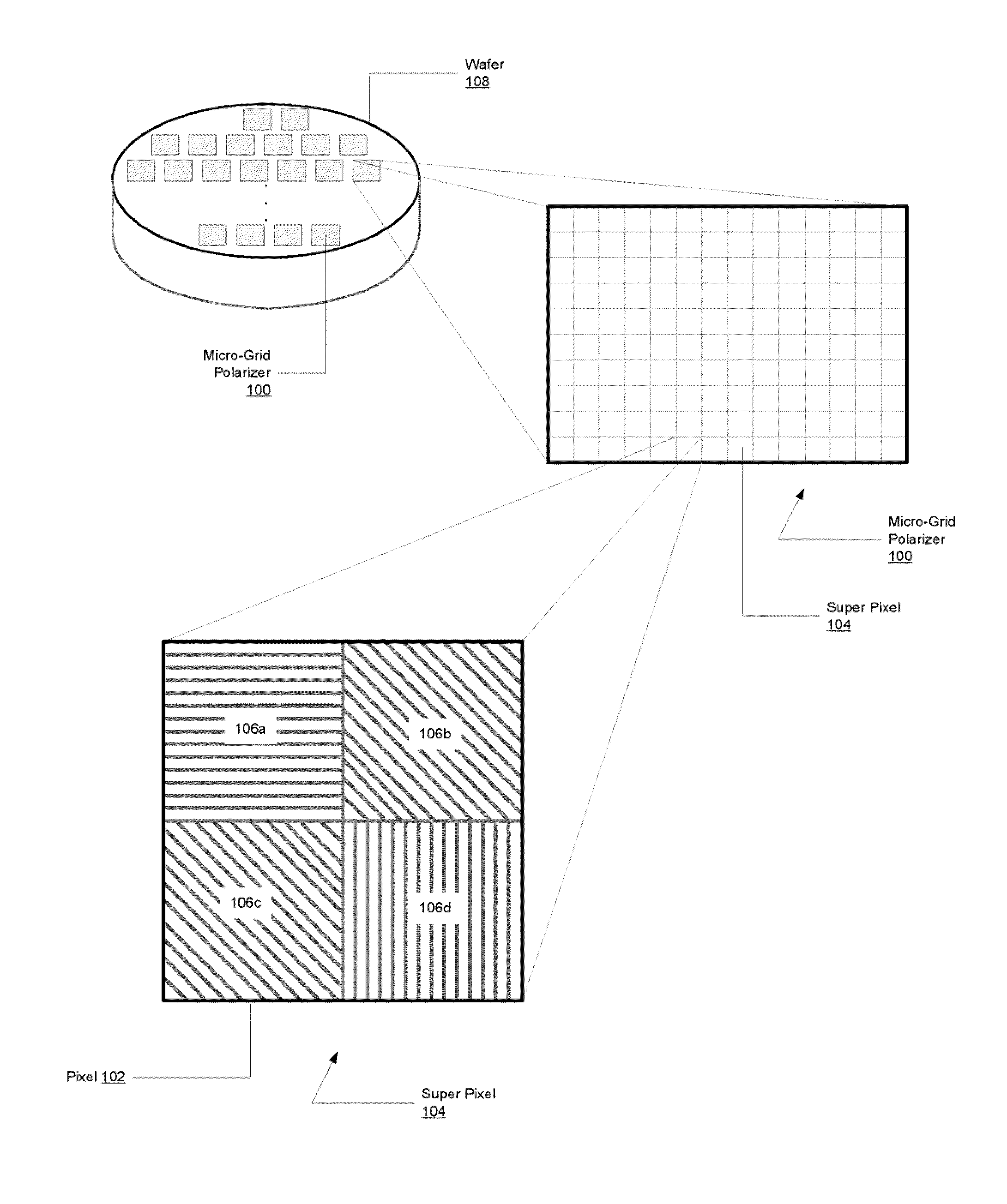
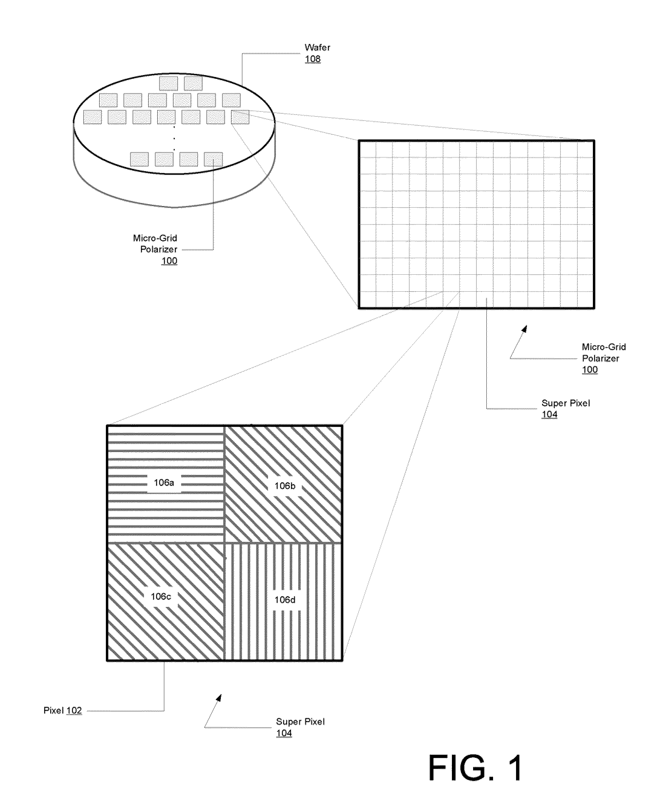
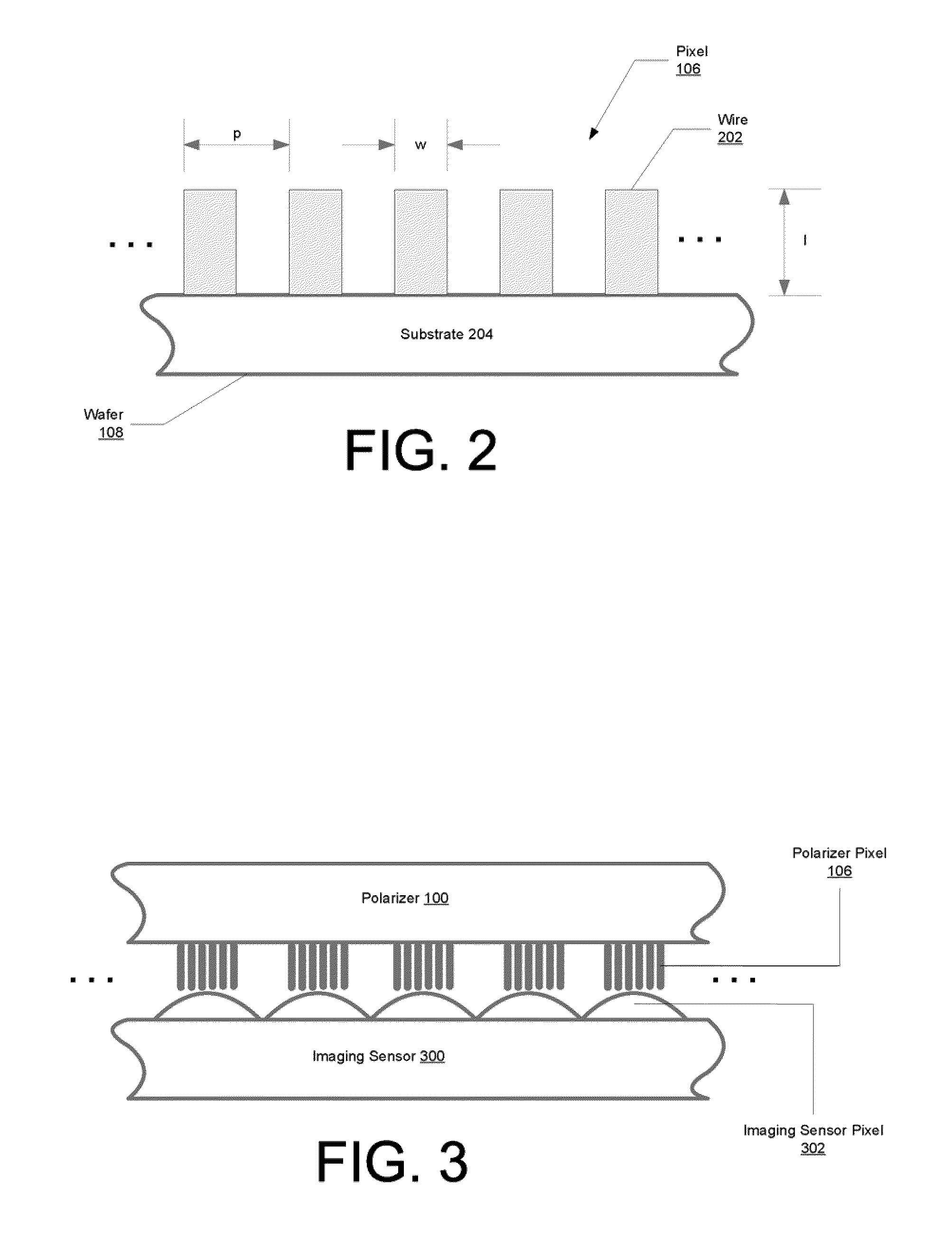
[0019]Described herein are methods for aligning a pixilated micro-grid polarizer to an image sensor having multiple pixels. In various embodiments of the invention, the micro-grid polarizer may be fashioned in checkerboard-style (meaning that the orientation of an individual pixel is different than that of its immediate neighbor pixels), with each pixel of the polarizer configured to pass light of a certain polarization state and arranged into “super pixel” groups of adjacent pixels. For example, one such polarizer may include super-pixels of 2×2 four adjacent pixels, configured to pass light of a polarization oriented in top-left 0°, top-right 45°, lower-left 135°, lower-right 90°, with the definition of 0° direction arbitrarily chosen to be along the row direction of the sensor. The pixels of the polarizer correspond to pixels of ideally the same pixel dimensions and pixel pitch, at least close enough such that within the longest separation distance across the chip the cumulative ...


PUM


Abstract

Aligning a cut-to-size (off-wafer) pixilated micro-grid polarizer to a ready packaged imaging sensor having multiple pixels involves minimizing a separation distance between the two units and then aligning respective corresponding pixels of the pixilated micro-grid polarizer with the pixels of the imaging sensor using optical signals as position feedback during the alignment process. Once the alignment has been achieved, the micro-grid polarizer may be affixed to the imaging sensor, for example using optical epoxy glue.

Description

RELATED APPLICATION[0001]This application is a NONPROVISIONAL of and hereby claims priority to U.S. Provisional Patent Application No. 61 / 177,126, filed May 11, 2009, incorporated herein by reference.FIELD OF THE INVENTION[0002]The present invention relates to methods for aligning a pixilated micro-grid polarizer to a ready-to-run image sensor having multiple pixels.BACKGROUND[0003]Polarization is a property of electromagnetic waves, such as light, that describes the orientation of the oscillation of the waves. By convention, it is the orientation of the electric field component of an electromagnetic wave over one period of its oscillation that defines the wave's polarization. The state of polarization of an electromagnetic wave can be determined using polarimetry.[0004]To measure such polarization states, it is common to use polarizers as filters for image sensors (e.g., charged coupled devices (CCDs) or other sensors). The polarizers often are arranged in checkerboard fashion, wit...

Claims


Application Information

Patent Timeline
IPC IPC(8): H04N5/225
CPCH04N9/045G02B5/3025
Inventor LIN, SHIH-SCHONBENCUYA, SELIM S.WHITE, CHARLES ANTHONYHENDRICKS, DAVID
Owner EMERGENTVIEWS
Why Eureka
Try Eureka