

Earmuff and Headphone
a headphone and earmuff technology, applied in the direction of ear treatment, transducer details, electrical transducers, etc., can solve the problems of complex structure of the headphone and increase the number of parts, and achieve the effect of light weight and improved sound insulation
- Summary
- Abstract
- Description
- Claims
- Application Information
AI Technical Summary
Benefits of technology
Problems solved by technology
Method used
Image

Examples
first embodiment
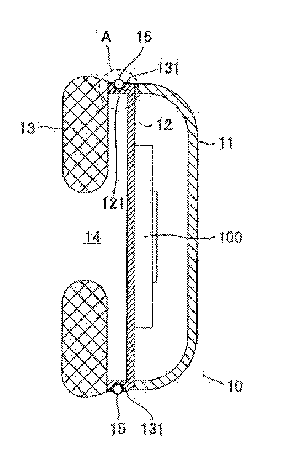
[0027]An embodiment of an earmuff according to the present invention is described below with reference to some of the drawings. FIG. 1 is a longitudinal sectional view exemplary illustrating an earmuff according to the present invention. In an earmuff 10 illustrated in FIG. 1, a baffle board 12 is fixed at an opening of an ear cup 11, and an ear pad 13 is fixed to the baffle board 12. The space surrounded by the baffle board 12 and the ear pad 13 is a front air chamber 14.
[0028]The baffle board 12 is a substantially circular member covering the opening of the ear cup 11. A rib 121 having a certain height is integrally formed on a peripheral surface of the baffle board 12. A flap 131 is a part of a skin member of the ear pad 13 serving as an engaging unit and is engaged to the periphery of the rib 121 by being constricted with an elastic force of a ring-shaped engagement member 15.
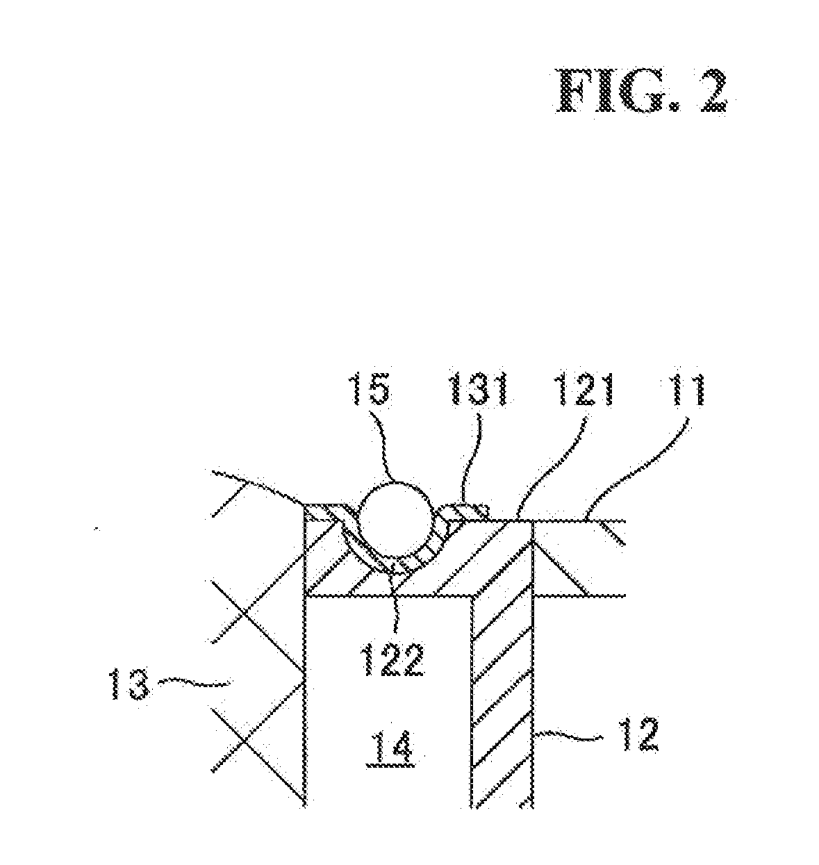
[0029]FIG. 2 is an enlarged view of a portion defined by the dotted circle in FIG. 1. As illustrated in ...
second embodiment
[0038]Another embodiment of an earmuff according to the present invention is described with reference to FIG. 4. An earmuff 10a illustrated in FIG. 4 includes a supporting member 123 that is an end portion of the rib 121 in the earmuff 10 described in the first embodiment, the end portion being extended in a direction towards the center of the baffle board 12.
[0039]The supporting member 123 supports the surface of the ear pad 13 facing the baffle board 12 at a certain position. Thus, a user can wear the earmuff 10a without the ear pad 13 sinking into the front air chamber 14 due to the pressure applied to the ear pad 13 in the direction towards the baffle board 12 upon wearing. In short, the supporting member 123 prevents the pressured ear pad 13 from sinking into the front air chamber 14. Therefore, the volume of the front air chamber 14 can be secured.
[0040]In the earmuff according to the present invention, the volume of the front air chamber can be made larger than that in the co...
third embodiment
[0042]Still another embodiment of an earmuff according to the present invention is described with reference to FIG. 5. An earmuff 10b in FIG. 5 includes a supporting member 124 on the front surface of the baffle board 12 of the earmuff 10 according to the first embodiment described above.
[0043]The supporting member 124 has a shape and a size capable of supporting the surface of the ear pad 13 facing the baffle board 12. Thus, a user can wear the earmuff 10b without the ear pad 13 sinking into the front air chamber 14 due to the pressure applied to the ear pad 13 in the direction towards the baffle board 12 upon wearing. The supporting member 124 does not necessary cover the whole circumference of the baffle board 12, and should be in a size (thickness, height, and length) small enough to secure the volume of the front air chamber 14.
[0044]In the earmuff according to the present invention, the volume of the front air chamber can be made larger than that in the conventional earmuff to...
PUM
 Abstract
Description
Claims
Application Information