
Apparatus for separating magnetic particles from liquids containing said particles, and an array of vessels suitable for use with such an apparatus

a technology of magnetic particles and liquid samples, which is applied in the direction of separation processes, laboratory glassware, instruments, etc., can solve the problems of corresponding plurality of transport means for moving the vessels, rapid diminishing of the magnetic force acting on the magnetic particles, and relatively slow desired transport of the magnetic particles to the pipetting tip

Inactive Publication Date: 2010-11-11
ROCHE MOLECULAR SYST INC
View PDF5 Cites 88 Cited by
  • Summary
  • Abstract
  • Description
  • Claims
  • Application Information

AI Technical Summary

Benefits of technology

[0028]According to a first aspect of the invention the above-mentioned first aim is achieved with a method according to claim 1 and with an apparatus according to claim 4. Further embodiments of the latter method are defined by claims 2 and 3. Further embodiments of the apparatus according to claim 4 are defined by claims 5 to 9.
[0029]According to a third aspect of the invention the above-mentioned third aim is achieved with an apparatus according to claim 12.
[0030]According to a fourth aspect of the invention the above-mentioned fourth aim is achieved with a vessel array according to claim 10. A certain embodiment of this vessel array is defined by claim 11.
[0031]The apparatuses according to the invention offer the advantage of providing the possibility of carrying out washing steps of the above-described type more rapidly, more effectively and with more efficient means, in particular in the case of parallel processing of liquids which contain magnetic particles and which are contained in a plurality of vessels.
[0032]The vessel array according to the invention is particularly advantageous for use with an apparatus according to the second aspect of the invention.

Problems solved by technology

A disadvantage of the latter apparatus is that the magnetic force that acts on the magnetic particles rapidly diminishes as the pipetting tip is moved away from the magnet, and the desired transport of the magnetic particles to the tip of the pipetting tip is thus relatively slow.
Another disadvantage of an apparatus of the kind described in U.S. Pat. No. 6,187,270 is that when it is desired to process in parallel liquids contained in a plurality of vessels, a corresponding plurality of transport means for moving the vessels away from the magnets are required.

Method used


Image

  • Apparatus for separating magnetic particles from liquids containing said particles, and an array of vessels suitable for use with such an apparatus
  • Apparatus for separating magnetic particles from liquids containing said particles, and an array of vessels suitable for use with such an apparatus
  • Apparatus for separating magnetic particles from liquids containing said particles, and an array of vessels suitable for use with such an apparatus

Examples


example 1

First Embodiment of an Apparatus According to the Invention

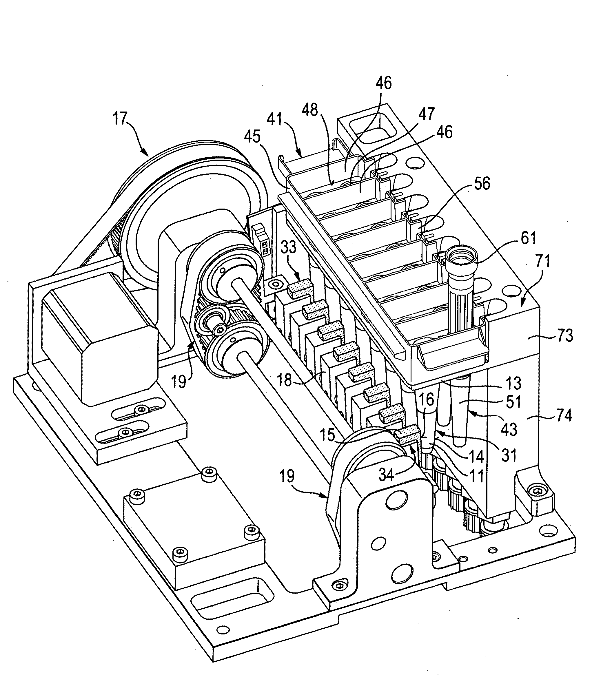
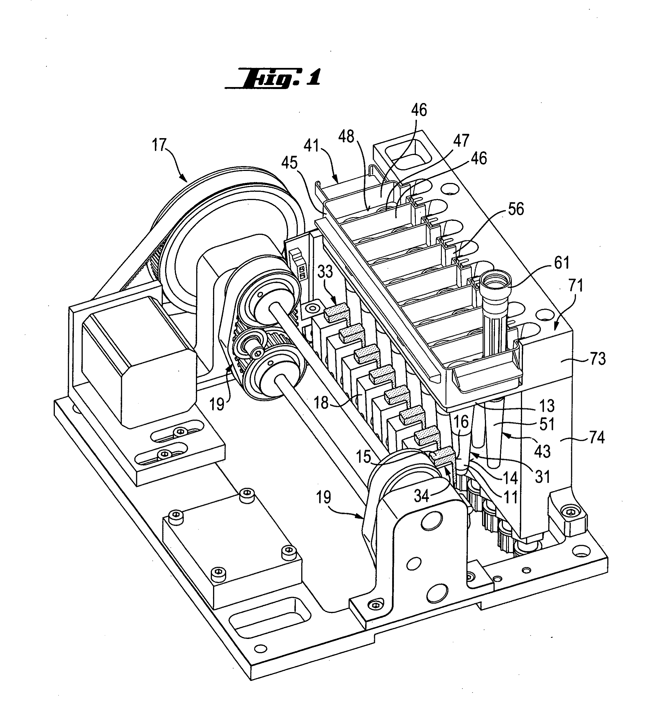
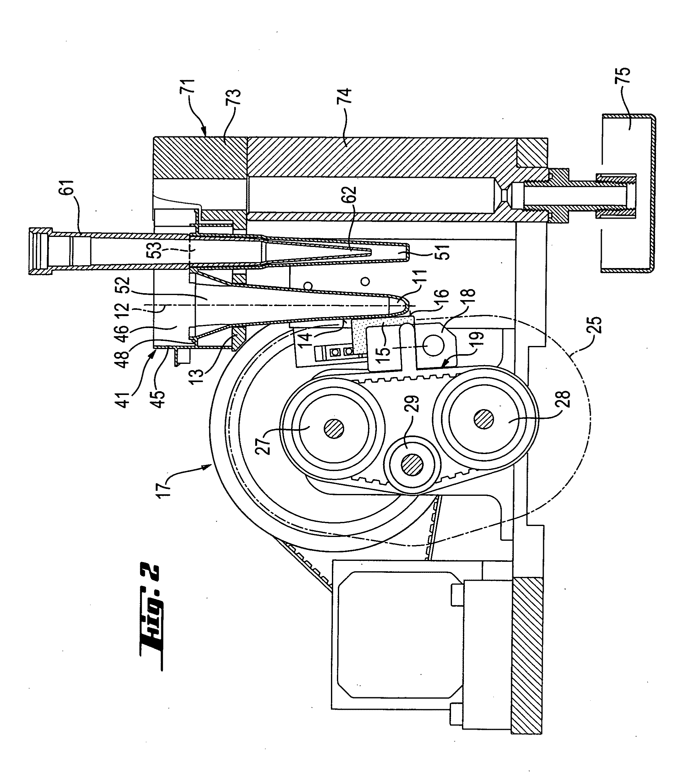
[0041]A first embodiment of an apparatus for separating magnetic particles from a liquid which contains such particles is described hereinafter with reference to FIGS. 1, 2, 5 and 6.

[0042]The apparatus shown in FIGS. 1 and 2 comprises a vessel holder 13. A liquid which contains magnetic particles is contained in an elongated vessel 11 shown in FIGS. 1 and 2.

[0043]Vessel 11 has a length symmetry axis 12 and has a lower portion which includes the bottom part of vessel 11. The lower portion of vessel 11 has a tapered cross-section that diminishes towards the bottom of the vessel. The lower portion of vessel 11 has a side wall 14. Side wall 14 has an outer surface which has a conical shape. Therefore, the intersection of the outer surface of side wall 14 with a plane that passes through the length axis 12 of vessel 11 forms a small angle with the length axis 12.

[0044]Vessel 11 is arranged in vessel holder 13 with the length axis...

example 2

First Embodiment of a Method According to the Invention

[0053]A method for separating magnetic particles from a liquid which contains such particles can be carried out according to the invention with the apparatus embodiment of example 1 described above with reference to FIGS. 1, 2, 5 and 6. According to this method a magnet 15 having a plane outer surface 16 is moved automatically along a motion path 25 so that over a portion of motion path 25 which extends from the above-mentioned first predetermined position to the second predetermined position, the plane outer surface 16 of magnet 15 is in contact with a portion of the outer surface of side wall 14 of the lower portion of vessel 11, and magnet 15 is moved downwards and towards the length axis 12 of vessel 11, when it is moved along the above mentioned portion of motion path 25.

[0054]In a certain embodiment a force is exerted on magnet 15 in order to press the plane outer surface 16 of magnet 15 on the outer surface of the side wa...

example 3

Second Embodiment of an Apparatus According to the Invention

[0056]A second embodiment of an apparatus for separating magnetic particles from a plurality of liquids which contain such particles is described hereinafter with reference to FIGS. 1 to 7.

[0057]The apparatus shown in FIGS. 1 and 2 comprises a vessel holder 13 adapted for receiving an array 31 of vessels 11. Each of the liquids which contain magnetic particles is contained in one of vessels 11.

[0058]Each vessel 11 has a length symmetry axis 12 and a lower portion which includes the bottom part of vessel 11. The lower portion of vessel 11 has a tapered cross-section that diminishes towards the bottom of the vessel. The lower portion of vessel 11 has a side wall 14. Side wall 14 has an outer surface which has a conical shape. The intersection of the outer surface of side wall 14 with a plane that passes through the length axis 12 of vessel 11 forms a small angle with the length axis 12.

[0059]The vessels 11 of array 31 are arr...


PUM

PropertyMeasurementUnit
angleaaaaaaaaaa
angleaaaaaaaaaa
magneticaaaaaaaaaa

Abstract

An apparatus for separating magnetic particles from a liquid which contains said particles, said liquid being contained in an elongated vessel (11) having a length axis (12), said vessel being arranged in a vessel holder (13) with its length axis (12) in a substantially vertical position, said vessel (11) having a bottom and a tapered cross-section that diminishes towards the bottom of the vessel and a side wall (14) which has an outer surface which forms an angle with the length axis (12) of said vessel (11). This apparatus comprises a magnet (15) having a plane outer surface (16) and being adapted for being moved by transport means (17) along a motion path (25), said magnet (15) and said transport means (17) being so arranged with respect to said vessel (11) that over a portion of said motion path (25) said plane outer surface (16) of said magnet is in contact with a portion of said outer surface of said side wall (14) of said vessel (11), and transport means (17) for moving said magnet (15) between a first predetermined position and a second predetermined position along said motion path (25).

Description

CROSS-REFERENCES TO RELATED APPLICATIONS[0001]The present application claims the benefit of EP Appl. No. 06075785.3 filed Mar. 31, 2006, the entire contents of which is hereby incorporated herein by reference in its entirety.FIELD OF THE INVENTION[0002]The present application relates to the field of devices for magnetic separation of an analyte from a liquid sample as used for example in immuno- or nucleic acid diagnostic assays.BACKGROUND OF THE INVENTION[0003]Magnetic particles are used as solid phase for performing some diagnostic assays, e.g. immunoassays. Such assays comprise magnetic particles in suspension in a reaction solution contained in a vessel. When the assay is conducted, it is at some steps necessary to separate the magnetic particles from the liquid contained in the vessel.[0004]In a known apparatus this is done by attracting the magnetic particles to the walls of the vessel by means of a magnet positioned close to the outer side wall of the vessel and by extracting...

Claims


Application Information

Patent Timeline
Patent Type & Authority Applications(United States)
IPC IPC(8): B03C1/12B01L9/00
CPCB01L3/5085B01L9/543B03C1/12G01N35/0098B03C2201/18B03C1/02B03C1/288B03C1/0332B03C1/01
Inventor HOLENSTEIN, TOBIASSCHNEEBELI, ROLFBELZ, RENATO
Owner ROCHE MOLECULAR SYST INC
Learn More