Fluid ejection device

a technology of ejection device and fluid, which is applied in the direction of valve arrangement, check valve, functional valve type, etc., can solve the problems of long time-consuming maintenance, inability to offer sufficient reliability to guarantee, and inability to maintain such devices, etc., to achieve the effect of reducing load loss

Inactive Publication Date: 2010-11-18
AIRBUS OPERATIONS (SAS)
View PDF23 Cites 3 Cited by
  • Summary
  • Abstract
  • Description
  • Claims
  • Application Information

AI Technical Summary

Benefits of technology

[0023]According to this embodiment, it is preferable that the axle of the pivot be connected to the seal and that it has, among other things, the possibility of translating in a plane more or less parallel to the ejection flow. Thus, the seal is broken by shear in a translation movement, then the broken section retracts by rotation around the pivot. Advantageously, the translation guide means can be extended in an oblique direction in relation to the flow so that the broken section of the seal is retracted to against one of the walls of the ejection port thus minimising the load losses.
[0024]According to a particular embodiment, the broken section of the seal located in the ejection flow has a profile favouring its retraction by rotation and / or by translation by hydrodynamic effect. This thus avoids this section of the seal, once retracted, from returning to its position under the effect of its own weight or prevents it from flapping in the fluid ejection flow.
[0025]The device according to the disclosed embodiments, which includes few moving parts liable to seize, is especially reliable and can advantageously be used as safety device on an aircraft.

Problems solved by technology

Such devices can however remain inactive for long times (several years) whilst being submitted to severe environmental conditions such as humidity, frost and high thermal amplitudes.
Consequently the valve systems, which imply the presence of moving parts and sealing constraints between the parts in relative movement, do not, in general, offer sufficient reliability to guarantee when the time comes the operation of the device.
These frequent inspections have a direct influence on the maintenance cost of such devices.
Such a screen comprises an obstacle disturbing the flow of the fluid and generating a load loss penalising for the efficiency of the fluid ejection device.
Such a foil is capable of breaking in an almost instantaneous manner under the effect of a pressure threshold thus favouring rapid ejection of the fluid whereas a more flexible membrane is liable to break in an incomplete manner then causing load losses during the ejection of the fluid.

Method used


Image

  • Fluid ejection device
  • Fluid ejection device
  • Fluid ejection device

Examples


second embodiment

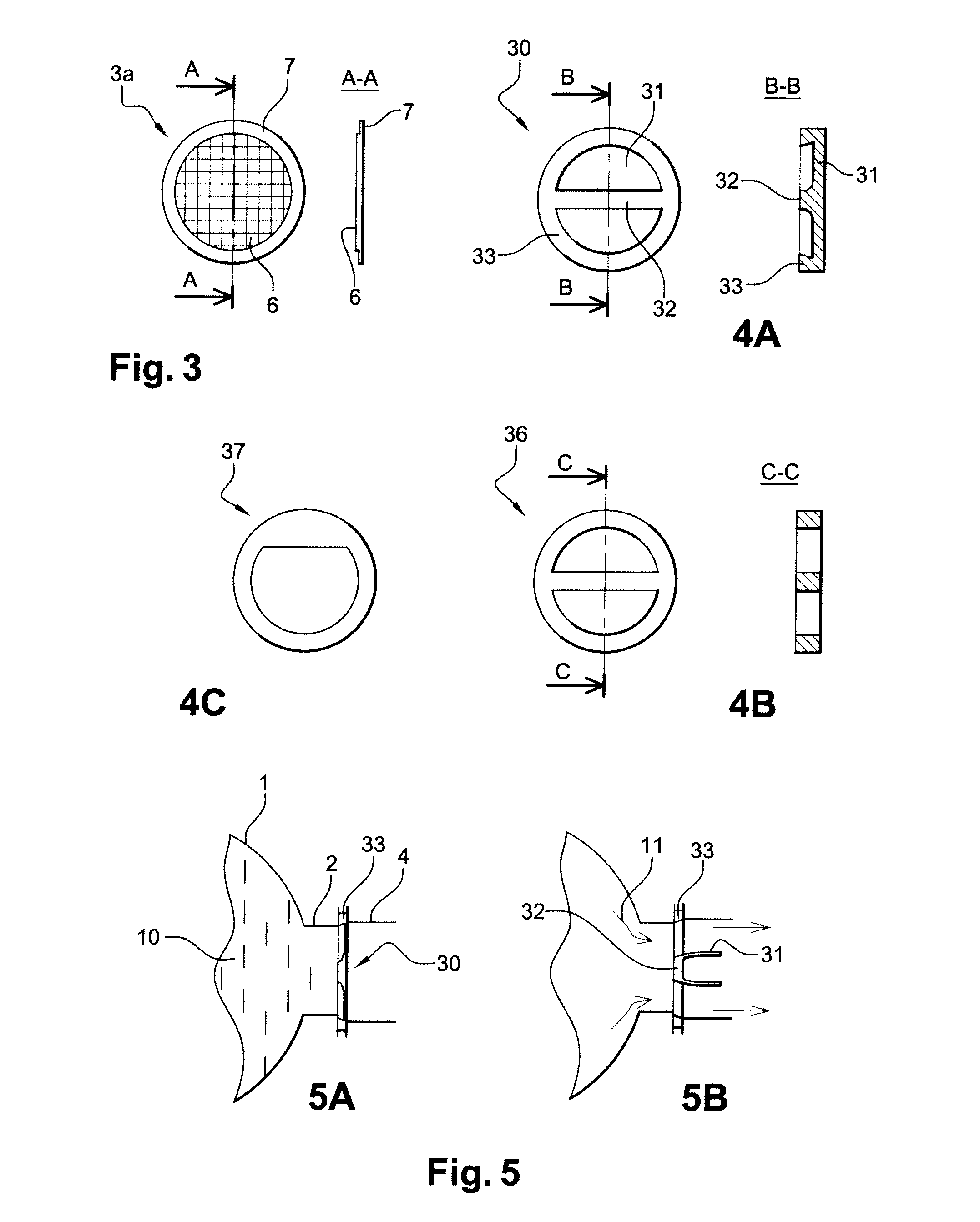
[0052]According to this second embodiment, FIG. 4A, the seal (30) includes a peripheral zone of higher thickness (33) and a central reinforced zone (32). A section with lower thickness (31) extends between these two reinforced zones.

[0053]Advantageously, the junction between the peripheral reinforced zone (33) and the thin section (31) has a profile capable of favouring breakage initiations on its periphery whereas the junction between the central reinforced zone (32) and the thin section (31) has on the contrary a profile limiting the stress concentrations. The junction of the central section (31) of the seal with its peripheral zone (33) comprises therefore a weakened zone capable of favouring and initiating the breakage of the seal.

[0054]FIG. 5A, the seal (30) is installed between the ejection port (2) and the end of the distribution circuit by gripping its reinforced peripheral zone (33) between two flanges. The peripheral ends of the central reinforced section (32) are also gri...

first embodiment

[0055]This embodiment is more reliable but the manufacture of the seals (30) is more complex to do economically for small series. Alternatively, FIG. 4B, a similar result can be obtained by using a composite seal. In this case, a part (36) corresponding to the contour of the peripheral section (33) and the central reinforced zone (32) is punched out from a metallic foil. Then a composite seal (3a) the structure of which, partially reinforced by the fibres, is equivalent to that of the corresponding variant of the first embodiment is added to this part (36), for example by bonding. When the pressure reaches a critical threshold, the central composite section (6) fails at the periphery but remains held by the foil (36) in the central zone, foil which is in this case dimensioned so as not to fail under the effect of the pressure.

[0056]According to this embodiment of the seal (30), it is also possible to use a reinforcement foil (37) the form of which allows a pivot to be made in an off...

third embodiment

[0059] FIG. 6, the seal (300) consists of an assembly of items including:

[0060]a foil sheet (301), preferably metallic and of a section sufficient to cover the complete tank port,

[0061]the said sheet is gripped, in its central section (301b), between two flanges (303) by means of screws (310) passing through the two flanges and the said sheet,

[0062]the said screws (310) are screwed transversally into an axle (320) longer than the width of the flanges which is thus solidly attached to the flanges and to the foil sheet.

[0063]The assembly consisting of the flanges (303), the axle (320) and the foil (301) thus assembled, is installed in a yoke (350) including a conduit the section of which has a form adapted to fit around the flanges (303) with a slight peripheral clearance. The yoke (350) includes two slots (321) capable of accommodating the two ends of the axle (320). For this purpose, the yoke can be made in two parts, or alternatively, the axle (320) can be initially slid through th...


PUM


Abstract

The disclosed embodiments relate to a pressurised fluid ejection device. More especially, the disclosed embodiments relate to such a device especially intended for fire fighting with improved reliability and efficiency, especially concerning the device placing the tank in communication with the fluid distribution circuit, including: a tank containing fluid, a fluid ejection port, ejection port closing means, a device capable of opening the said closing means including a breakable seal and means capable of retaining the seal after breakage comprising a pivot with an axis perpendicular to the ejected fluid flow.

Description

CROSS-REFERENCE TO RELATED APPLICATIONS[0001]This application claims priority to French Application No. 09 53187, filed on 14 May 2009, the disclosure of which is incorporated herein by reference in its entirety.BACKGROUND[0002]1. Field[0003]The disclosed embodiments relate to a pressurised fluid ejection device. More especially, the disclosed embodiments relate to such a device especially intended for fire fighting.[0004]Pressurised fluid ejection devices such as extinguishers for fire fighting are placed in two categories:[0005]devices under permanent pressure in which a gas ensures the permanent pressurisation of a fluid within a unique cylinder acting as tank,[0006]devices under non-permanent pressure in which the fluid contained in the tank is pressurised only at time of its ejection: this pressurisation can be ensured by placing the tank containing the fluid in communication with a compressed gas source or by mechanical means such as the movement of a piston tending to reduce ...

Claims


Application Information

Patent Timeline
Patent Type & Authority Applications(United States)
IPC IPC(8): A62C35/68
CPCA62C35/023F16K15/141F16K15/03
Inventor FABRE, CHRISTIANBIGNOLAIS, ALAIN
Owner AIRBUS OPERATIONS (SAS)
Why Eureka
Try Eureka