Integrated lighting system and method

a lighting system and integrated technology, applied in the field of lighting systems, can solve the problems of not having typical classroom lighting solutions do not meet the functional needs of teachers or students, and most existing systems do not have the flexibility to provide high-quality lighting

Active Publication Date: 2010-11-18
HUBBELL LIGHTING INC
View PDF101 Cites 21 Cited by
  • Summary
  • Abstract
  • Description
  • Claims
  • Application Information

AI Technical Summary

Benefits of technology

[0012]Another exemplary embodiment of the invention provides a system and method where a lighting system can be set up and tested and then the configuration saved in a portable memory, such as on a memory card. For example, a memory card can be transferred to another system where it is read to facilitate faster and easier configuring of the other system to parallel, or to be exactly like, the original system.
[0014]According to yet another exemplary embodiment of the invention, a system and method provide for switching between different mutually exclusive lighting modes where the lighting of each mode is sequenced such that the second lighting mode is initiated before the first mode is terminated, resulting in a continuity of lighting in the controlled area.

Problems solved by technology

Most existing systems don't have the flexibility to provide high-quality lighting in this varying environment.
Typical classroom lighting solutions do not meet the functional needs of teachers or students.

Method used


Image

  • Integrated lighting system and method
  • Integrated lighting system and method
  • Integrated lighting system and method

Examples


Embodiment Construction

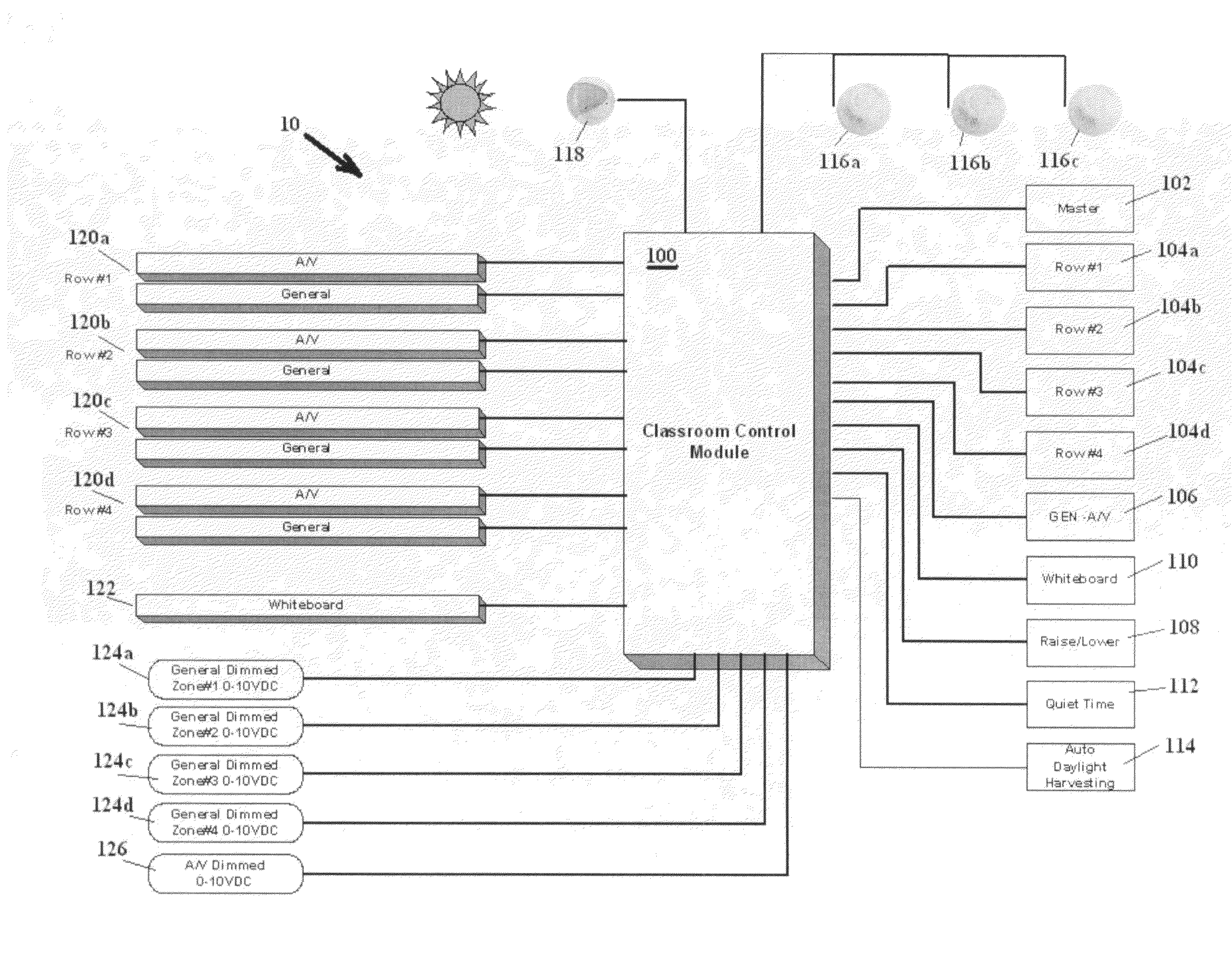
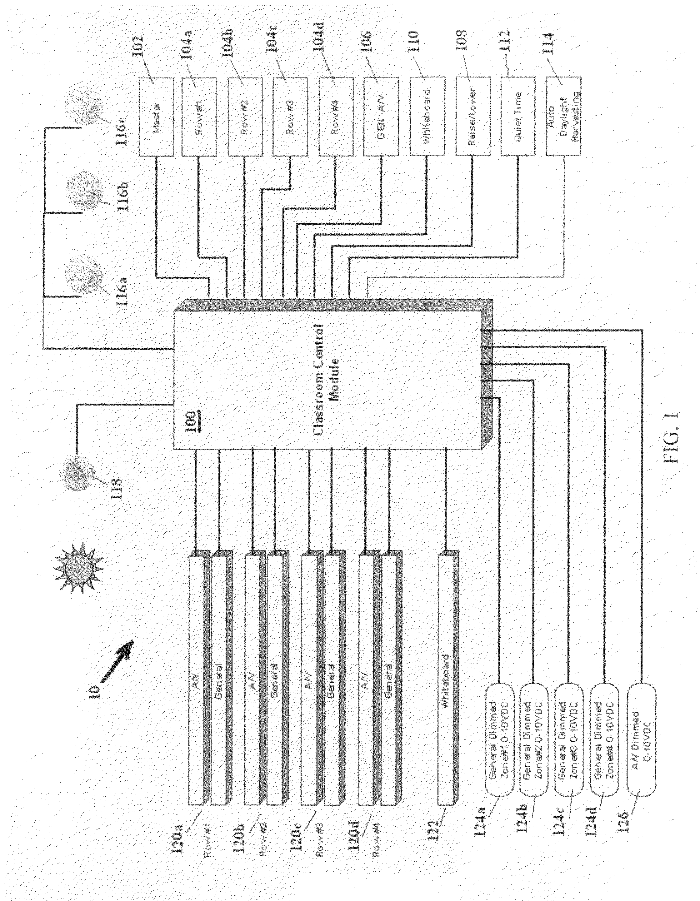
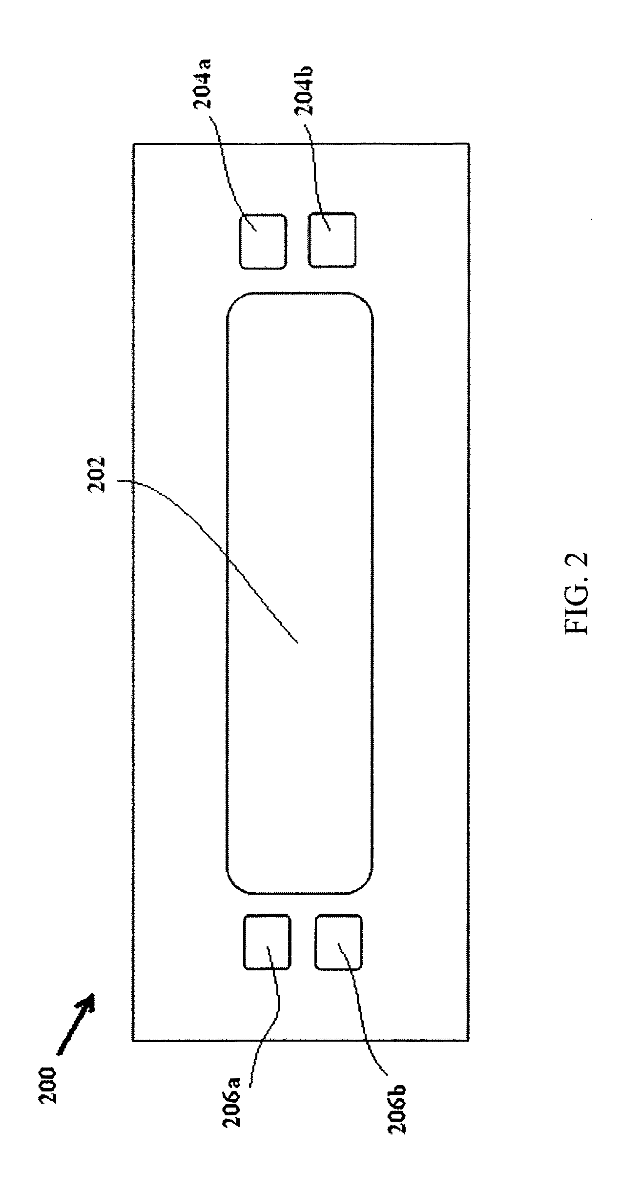
[0026]Referring now to the drawings, wherein like reference numerals designate identical or corresponding parts throughout the several views, embodiments of the present invention are shown in schematic detail.

[0027]The matters defined in the description such as a detailed construction and elements are nothing but the ones provided to assist in a comprehensive understanding of the invention. Accordingly, those of ordinary skill in the art will recognize that various changes and modifications of the embodiments described herein can be made without departing from the scope and spirit of the invention. Also, well-known functions or constructions are omitted for clarity and conciseness. Exemplary embodiments of the present invention are described below in the context of a classroom application. Such exemplary implementations are not intended to limit the scope of the present invention, which is defined in the appended claims.

[0028]According to exemplary embodiment of the present inventio...


PUM


Abstract

System and method are provided where a plurality of luminaires, control switches, occupancy detectors, and photocells are connected to a central control module including a user interface which is used for setting up, testing, commissioning and maintaining the system; a memory card interface and associated memory card which can be used to load and save configuration data, update firmware, and log system operation. Lighting system can be set up and tested and then the configuration saved in a portable memory, such as on a memory card which can be transferred to another system where it is read to facilitate faster and easier configuring of the other system to parallel, or to be exactly like, the original system. Data stored on a portable memory can be automatically recognized to perform appropriate actions such as, for example: update configuration, or update firmware. Also provided is switching between different mutually exclusive lighting modes where the lighting of each mode is sequenced such that the second lighting mode is initiated before the first mode is terminated, resulting in a continuity of lighting in the controlled area. Other features include daylight harvesting control with multiple zone dimming and switching, programmable attack and decay dimming rates, the ability to return a system to its previous dimming level after the lights have been turned off, and the ability to start the controlled lights at full light level then dim down to the previous level to ensure the lighting ballast have sufficient voltage to start up.

Description

CROSS-REFERENCE TO RELATED APPLICATION[0001]This application claims benefit under 35 U.S.C. §119(e) provisional patent application Ser. No. 61 / 175,343 filed on May 4, 2010, the entire disclosure of which is hereby incorporated by reference.BACKGROUND OF THE INVENTION[0002]1. Field of the Invention[0003]The present invention generally relates to systems and methods for controlling area lighting. More particularly, the present invention relates to lighting systems and methods for controlling indoor lighting by providing flexible and programmable control based on occupancy and daylight contribution.[0004]2. Discussion of the Background[0005]Indoor facilities such as classrooms require robust, capable and flexible lighting and control solutions that serve the user and save energy. Static lighting systems designed to IES specifications service only a small portion of the actual lighting requirements that exist in today's classroom environment[0006]Complicating the design of these solutio...

Claims


Application Information

Patent Timeline
Patent Type & Authority Applications(United States)
IPC IPC(8): H05B37/02H05B44/00
CPCH05B37/0245H05B37/02H05B37/029H05B47/155H05B47/115H05B47/11H05B47/175H05B47/17
Inventor MIDDLETON-WHITE, STUARTSMITH, GREGORYMARTIN, ROBERTHARTNAGEL, THOMAS J.WEBER, THEODORE E.CRANE, MIKEARBOUW, TERRYKACK, DAWN R.RECTOR, DAVID J.
Owner HUBBELL LIGHTING INC
Why Eureka
Try Eureka