Exhaust gas purifying system

a technology of exhaust gas and purification system, which is applied in the direction of process and machine control, separation processes, instruments, etc., can solve the problem of maximization of catalysts

Inactive Publication Date: 2010-11-18
TOYOTA IND CORP
View PDF3 Cites 35 Cited by
  • Summary
  • Abstract
  • Description
  • Claims
  • Application Information

AI Technical Summary

Benefits of technology

[0009]In accordance with the present invention, an exhaust gas purifying system includes an exhaust passage, an oxidation catalyst, a selective catalytic reduction catalyst, a urea water supply device, a first heating mechanism and a controller. The exhaust gas discharged from an internal combustion engine flows through the exhaust passage. The oxidation catalyst for oxidizing nitrogen monoxide contained in the exhaust gas to nitrogen dioxide is disposed in the exhaust passage. The selective catalytic reduction catalyst is disposed downstream of the oxidation catalyst. The urea water supply device supplies urea water into the exhaust passage at the upstream of the selective catalytic reduction catalyst. The first heating mechanism heats the oxidation catalyst. The controller controls the first heating mechanism to adjust the temperature of the oxidation catalyst such that the molar ratio between nitrogen monoxide and nitrogen dioxide in the exhaust gas flowing into the selective catalytic reduction catalyst become one to one.

Problems solved by technology

Thus, if the exhaust gas purifying system disclosed in the above Publication is applied to the conventional urea SCR system, increasing the molar ratio of NO2 by heating the oxidation catalyst with the electric heater does not necessarily ensure that the molar ratio between NO and NO2 contained in exhaust gas flowing into the SCR catalyst becomes one to one and that purification efficiency of the SCR catalyst is maximized.

Method used


Image

  • Exhaust gas purifying system
  • Exhaust gas purifying system
  • Exhaust gas purifying system

Examples


Embodiment Construction

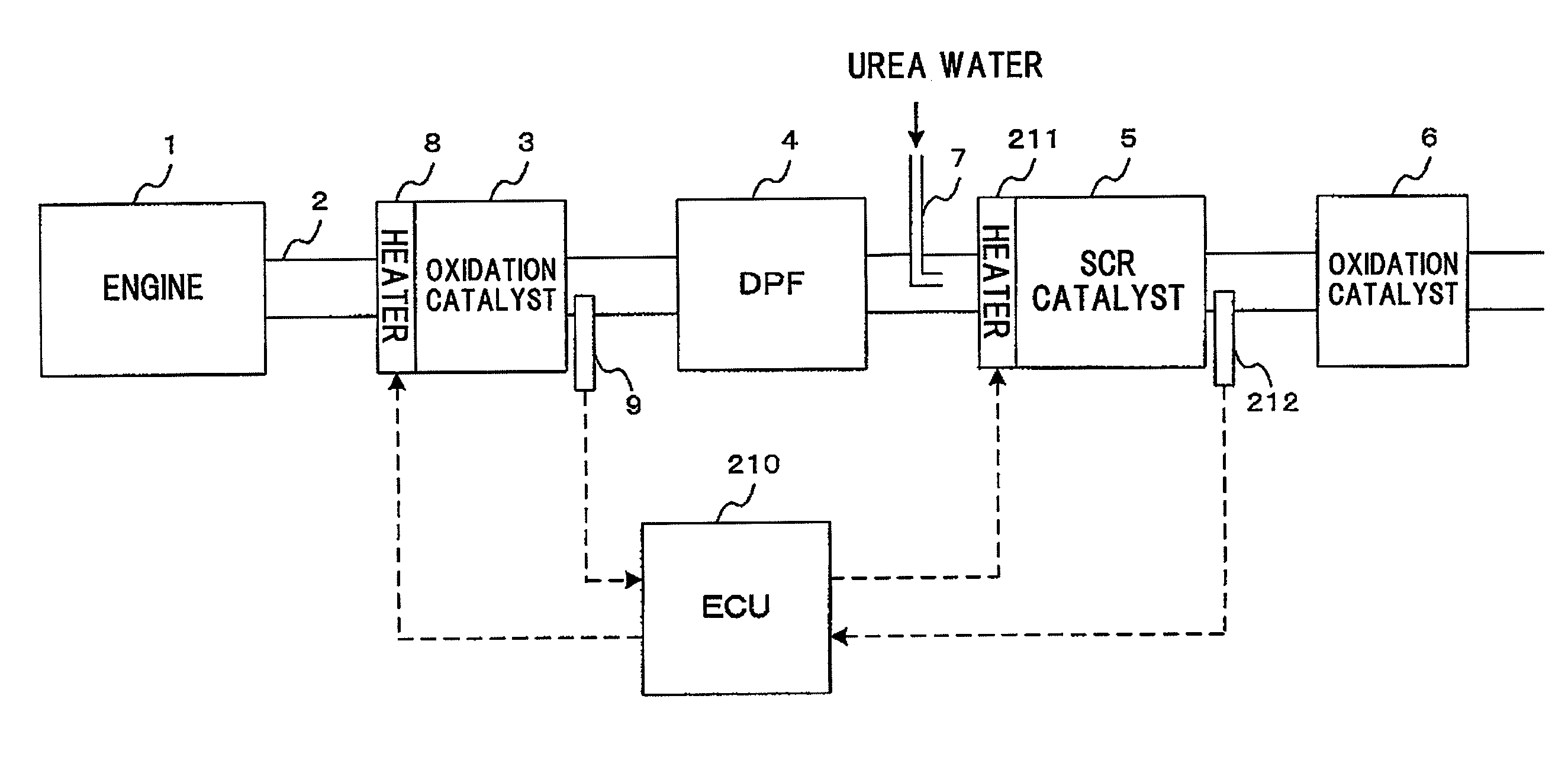
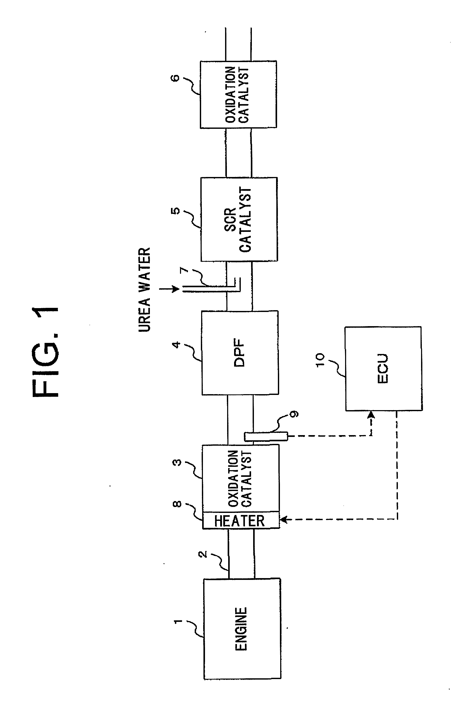
[0016]The following will describe an exhaust gas purifying system according to a first preferred embodiment of the present invention with reference to FIGS. 1 through 3. Referring to FIG. 1 showing the exhaust gas purifying system according to the first preferred embodiment of the present invention, an oxidation catalyst 3 for oxidizing a part of NO contained in exhaust gas thereby to form NO2 is disposed in an exhaust passage 2 through which exhaust gas discharged from a diesel engine 1 serving as an internal combustion engine flows. A diesel particulate filter (DPF) 4 for removing particulate matter (PM) contained in exhaust gas is disposed downstream of the oxidation catalyst 3. A selective catalytic reduction (SCR) catalyst 5 for reducing NOX to form nitrogen and water by reacting NOX with ammonia produced by hydrolysis of urea water is disposed downstream of the DPF 4. An oxidation catalyst 6 for oxidizing ammonia remaining in the SCR catalyst 5 without being reacted or consume...


PUM

PropertyMeasurementUnit
molar ratioaaaaaaaaaa
temperatureaaaaaaaaaa

Abstract

An exhaust gas purifying system includes an exhaust passage, an oxidation catalyst, a selective catalytic reduction catalyst, a urea water supply device, a first heating mechanism and a controller. The exhaust gas discharged from an internal combustion engine flows through the exhaust passage. The oxidation catalyst for oxidizing nitrogen monoxide contained in the exhaust gas to nitrogen dioxide is disposed in the exhaust passage. The selective catalytic reduction catalyst is disposed downstream of the oxidation catalyst. The urea water supply device supplies urea water into the exhaust passage at the upstream of the selective catalytic reduction catalyst. The first heating mechanism heats the oxidation catalyst. The controller controls the first heating mechanism to adjust the temperature of the oxidation catalyst such that molar ratio between nitrogen monoxide and nitrogen dioxide in the exhaust gas flowing into the selective catalytic reduction catalyst become one to one.

Description

BACKGROUND OF THE INVENTION [0001]The present invention relates to an exhaust gas purifying system, and more particularly to an exhaust gas purifying system including a urea selective catalytic reduction (SCR) system for purifying nitrogen oxides (NOX) contained in exhaust gas discharged from a diesel engine.[0002]The urea SCR system has been developed for reducing NOX contained in exhaust gas discharged from the diesel engine. In the urea SCR system, a catalyst known as SCR catalyst is used for purifying by reacting NOX with ammonia produced by hydrolysis of urea water to form nitrogen and water.[0003]Purification efficiency of the SCR catalyst is maximized when the molar ratio between nitrogen monoxide (NO) and nitrogen dioxide (NO2) is one to one. However, the content of NO in normal exhaust gas is usually greater than that of NO2. In order to make the molar ratio between NO and NO2 close to one to one, it has been practiced to provide an oxidation catalyst upstream of the SCR ca...

Claims


Application Information

Patent Timeline
Patent Type & Authority Applications(United States)
IPC IPC(8): B01D50/00G05D23/00B01D53/94
CPCF01N3/021F01N3/106F01N3/208Y02T10/24F01N2560/06F01N2560/14F01N2610/02F01N2240/16Y02T10/12
Inventor YOSHIDA, KOJIKATO, YOSHIFUMI
Owner TOYOTA IND CORP
Why Eureka
Try Eureka