
Ophthalmic sizing devices

a technology of ophthalmology and sizing device, which is applied in the field of medical devices, can solve the problems of eye brim with tears, eye irritation, and eye irritation, and achieve the effects of reducing the number of eye drops

Active Publication Date: 2010-11-18
LJT PROJECTS
View PDF7 Cites 2 Cited by
  • Summary
  • Abstract
  • Description
  • Claims
  • Application Information

AI Technical Summary

Problems solved by technology

Sometimes, if an unwanted closure of the passageways of the system occurs, for example by way of a blockage of any one or more of its sub-components, excess lacrimal fluid can no longer be disposed of in the usual way.
Such a blockage can result from, inter alia, congenital anomalies, accidents, inflammation, advancing age, and so forth, and tends to cause the eye to continuously brim over with tears, with concomitant discomfort to the individual.
More seriously, if the blocked tears stagnate, they can become infected, which can then lead to inflammatory irritation of the mucous membranes of the affected passage.
In turn this can result in proliferation of local epithelium, as well as hyperaemia, and even a purulent exudation into the conjunctiva.
Infection caused in this way can ultimately lead to scarring over of the canaliculi (4, 5).
In other cases, however, it may not be possible to re-connect or repair any part of the natural tear drainage system.
Occasionally, the new connection after a DCR operation may be patent but fail to drain tears.
Such operations to place bypass tubes have to date seldom been entirely successful, because at least the following two particular difficulties have typically been experienced.
Firstly, due to the lack of a firm attachment between the tube and the patient's tissues, as the tissues heal around the lower end portion of the inserted replacement tube, the latter is gradually rejected from the bone and flesh of the patient.
And secondly, the internal opening of the tube may become obstructed either by the patient's flesh tending to heal over this opening if the tube is too short, or through impacting the midline nasal septum if it is too long.
Firstly, the dipstick method determines the distance of the tip of the tube from the midline septum but, given that the space inside the nose is very different between individual patients, this provides no real accuracy regarding how far it is beyond the lateral wall.
Secondly, due to the flexibility and elasticity of the tissues in the medial canthal region where the external flange of the bypass tube will rest, the estimation of the total distance from the nasal septum to this point is inherently inaccurate.
Thirdly, a dipstick is merely a metal stick with a scale on its length that is held in the track created.
The track angle and / or direction may not be exactly the one that the tube will eventually lie on once it has been placed in situ, thus the length calculated by the dipstick method has another degree of inaccuracy.
Fourthly, the tip of the dipstick must contact the nasal septum and in doing so is liable to cause some trauma to the mucosa surface.
The tubes that have been placed in situ during this method that have been found to be of the incorrect size and thus removed could not be re-used in other patients even if cleaned and re-sterilised.
Hence, the actual total cost for bypass tubes used is usually higher than for the individual tube that is left in the patient at the end of the operation.
Whilst this in itself may not be a very significant extra expense when using relatively cheap standard tubes, the increasing use of newer frosted or collapsibly flanged tubes is made more expensive.

Method used


Image

  • Ophthalmic sizing devices
  • Ophthalmic sizing devices
  • Ophthalmic sizing devices

Examples


Embodiment Construction

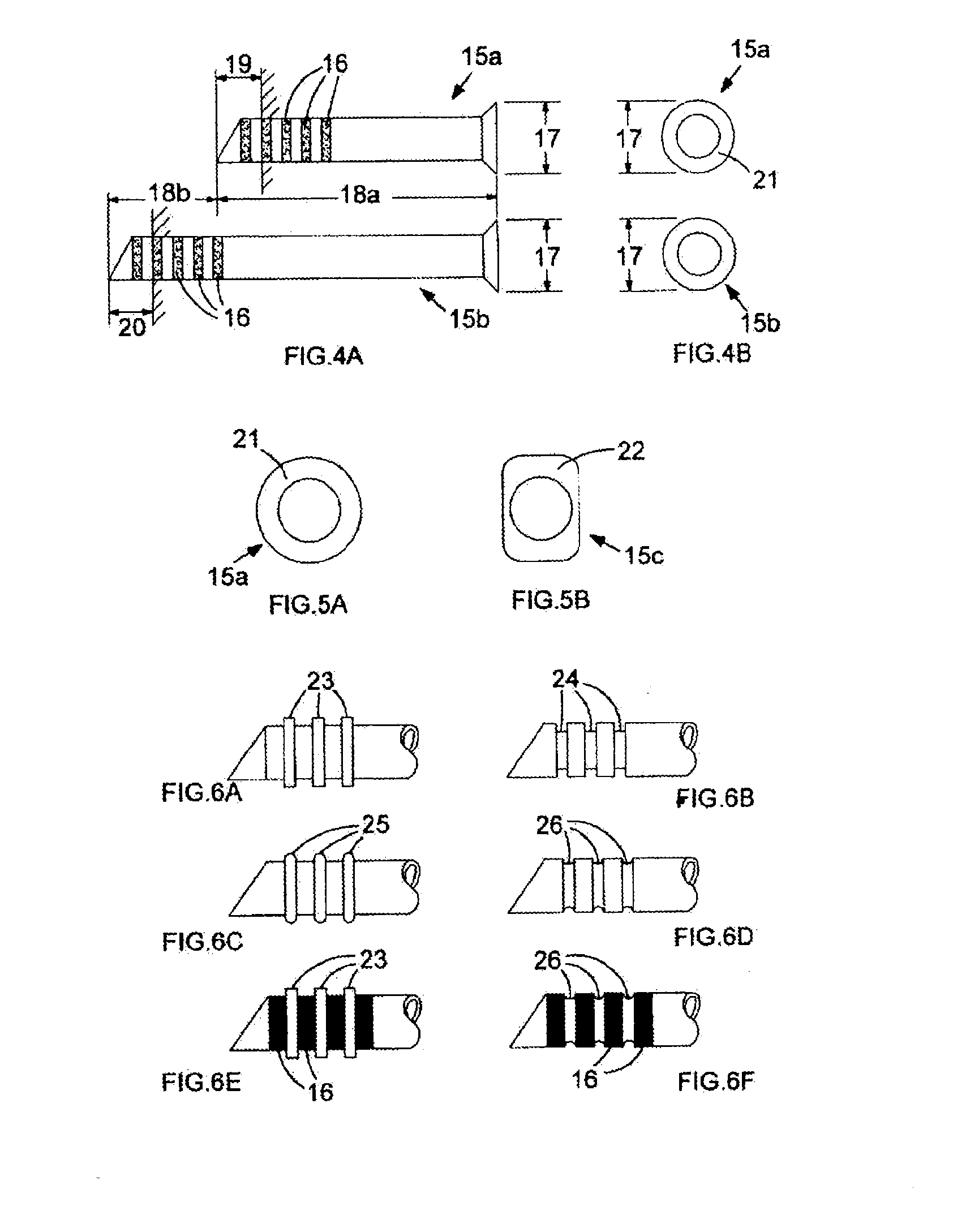
[0048]A set of two sizing devices 15a, b is shown in FIG. 4A. Each of these illustrated sizing devices is a tube having a lumen, although alternatively each device could be a solid cylindrical device (not shown), that is, being a device not having a lumen.

[0049]The tube illustrated in FIG. 4A has an easily visible series of marked bands 16 at an end furthest away from the flanged end that prevents it from passing too far down the surgically formed passage and secures it at the inner canthus 1 of the eye when it is in situ.

[0050]The marked bands are useful for determining not just the overall length of the bypass tube to be used in a permanent capacity, but also for determining the flange position for those bypass tubes that incorporate such an internal flange.

[0051]Often the base of these internal flanges is spread over, for example approximately 1.5 mm, its site on the respective bypass tube. To provide a clearer visual impression of where the flange will be relative to the lateral...


PUM


Abstract

An ophthalmic sizing device includes a sizing tube or set of such sizing tubes for use in determining a correct size of a bypass tube required in lacrimal surgery, each sizing tube having a flanged end at one end of a longitudinal length of tubing, the remaining end of the tubing distal to the flanged end having a series of ruled markings longitudinally along and towards the flange end. When used, a set of sizing tubes includes tubes having at least two relatively different absolute longitudinal lengths of tubing; and / or diameter flanges. The device can be in the form of a dilator having a sizing section. The use of such sizing devices allows the length of an ophthalmic bypass tube to be determined that leaves the tip of the bypass tube, when in situ, to protrude an optimally desired distance beyond the outer (lateral) nasal wall and into the nasal cavity of each particular patient, while remaining clear of the midline septum. Such a proud projection of bypass tubing helps prevent the bypass tube from being blocked after its permanent insertion.

Description

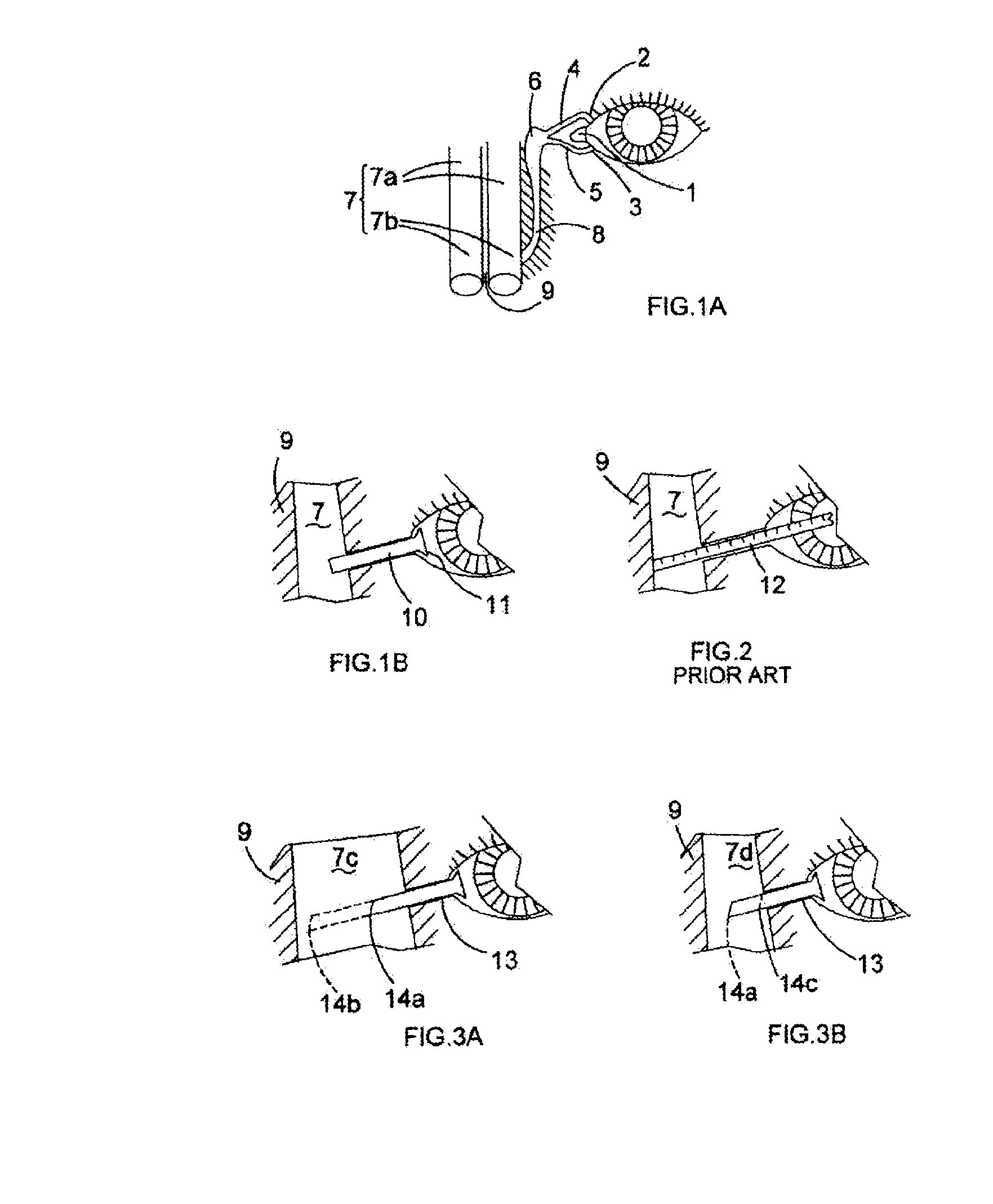
TECHNICAL FIELD[0001]The present invention relates to medical devices that have their main application in corrective tear-duct surgery.BACKGROUND ART[0002]In healthy individuals, tear fluid (that is “lacrimal” fluid) is normally supplied continuously to their eyes from lacrimal glands, each being located in a lateral and superior relation to the respective eye. Upper lacrimal ducts feed the fluid from each gland to a respective conjunctival sac, in which the relevant eyeball is partially encased. The lacrimal fluid subsequently washes the sclera and other conjunctival components of the eye, as well as its cornea.[0003]Under such healthy conditions, excess lacrimal fluid that cannot be retained by each eye and conjunctiva tends to be drained (see FIG. 1 of the drawings accompanying this specification) from the inner-canthus (1) (at the corner of the eye) to the nasal passages (7a,b), in particular to the inferior nasal meatus (7b). The nasal passages are separated by the nasal septum...

Claims


Application Information

Patent Timeline
Patent Type & Authority Applications(United States)
IPC IPC(8): A61B5/107
CPCA61F9/00772
Inventor PEARSON, ANDREW ROBERT
Owner LJT PROJECTS
Learn More