
Burner for gas boiler

a gas boiler and burner technology, applied in the field of burners for gas boilers, can solve the problems of increasing material costs and manufacturing costs, reducing the life of burners, and difficult to produce combustion, so as to reduce the generation of co, improve the flame holding effect, and reduce the effect of generating co

Inactive Publication Date: 2010-11-25
KYUNGDONG NAVIEN
View PDF7 Cites 11 Cited by
  • Summary
  • Abstract
  • Description
  • Claims
  • Application Information

AI Technical Summary

Benefits of technology

[0017]As described above, a burner for gas boiler according to the invention can replace existing circular burners or instantaneous bar type burners, improve the flame holding effect by forming main fire holes at an angle, and maintain the fire by constantly supplying secondary air between the main fire holes. Further, it is possible to achieve an environment-friendly boiler by reducing generation of CO, NOx, etc., because the performance of combustion is considerably improved. Furthermore, since the upper plate and lower plate of the burner main body can be made of different materials, the cost is reduced, and it is possible to reduce the width of the burner by reducing the length of the flame of the burner.
[0018]In addition, the entire size of the boiler is reduced, such that it is possible to obtain additional effects in transport, installation, etc.

Problems solved by technology

Therefore, it was difficult to produce combustion when gas pressure that is supplied decreases, such as rush hour, or the gas decreases in volume due to low temperature of the external air.
Further, because fire holes are formed at the side of the burner cover, lifting of flame was generated when the second air was supplied perpendicular to the fire holes, causing a bad combustion of the flames above the fire holes due to the lack of second air, and the upper plate of the burner was overheated due to the concentration of heat, thereby reducing the burner's life.
In addition, a plurality of separate burners is provided, thereby increasing material costs and manufacturing cost.

Method used


Image

  • Burner for gas boiler
  • Burner for gas boiler
  • Burner for gas boiler

Examples


Embodiment Construction

[0021]Embodiments of a burner for a gas boiler according to the invention, having the above configuration, are described hereafter with reference to the accompanying drawings.

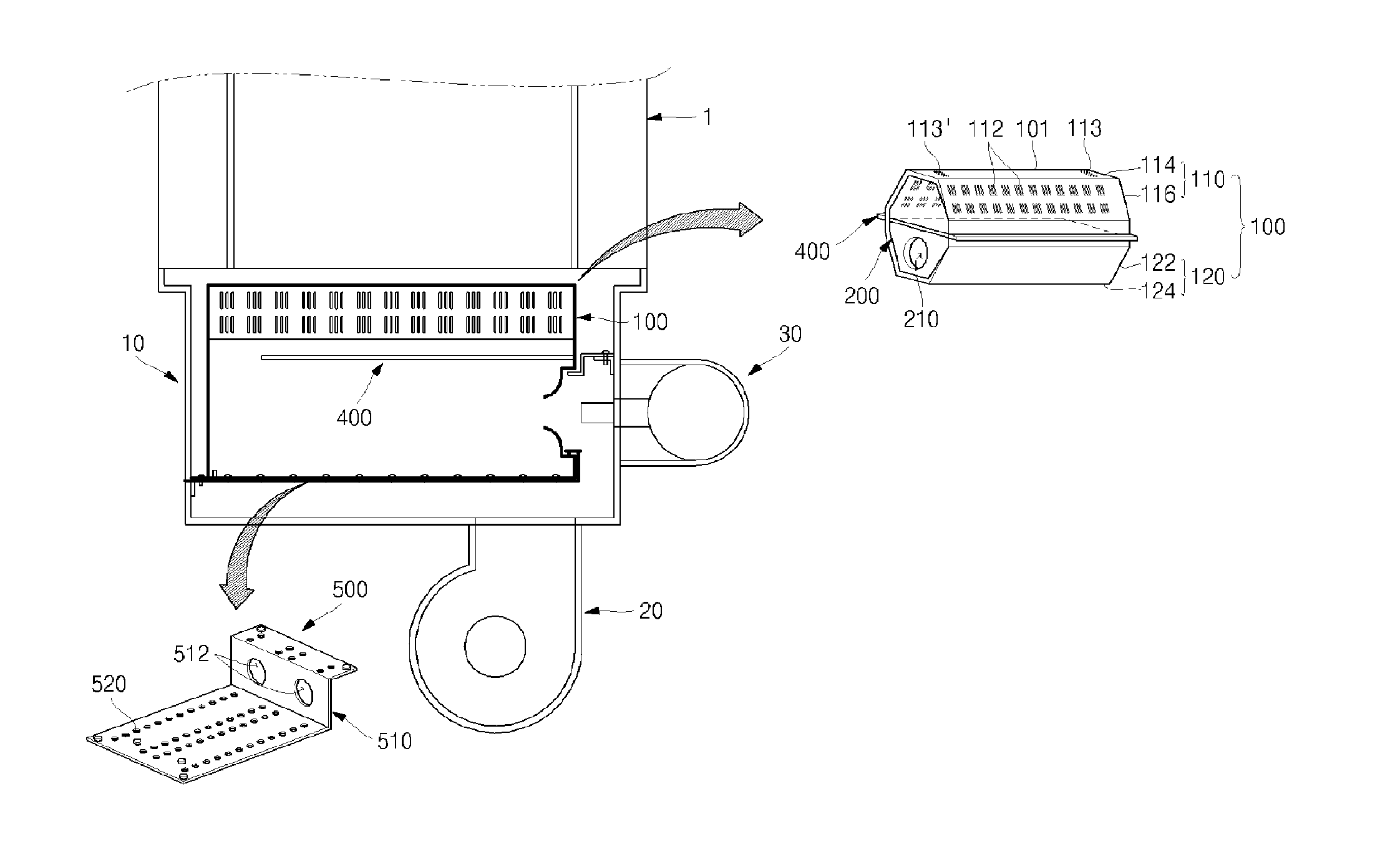
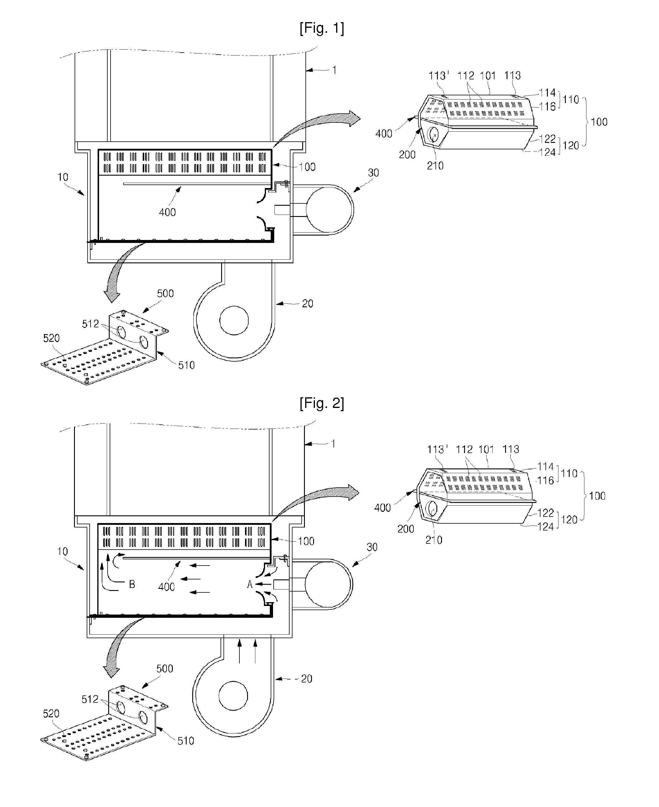
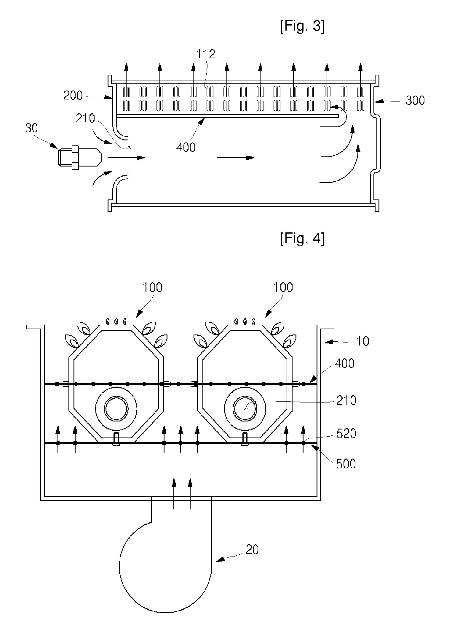
[0022]FIG. 1 is a view illustrating the configuration of a burner for a gas boiler according to the invention and FIGS. 2 to 4 are views illustrating the operation of a burner for a gas boiler according to the invention.

[0023]Referring to FIG. 1, a burner includes: a casing 10 that has a space inside; a fan 20 that is connected to the lower side of the casing 10 and supplies the external air into the casing 10; a nozzle unit 30 that is connected to a side of the casing 10 and injects gas at high speed through the front end disposed inside the casing 10; and a burner main body 100 that is disposed from a predetermined distance from the bottom of the casing 10 and has a burner upper plate 110 having main fire holes 112 formed at regular distances at both sides in the longitudinal direction of a burner body 101 an...


PUM


Abstract

The present invention relates to a burner for gas boiler that produces stable combustion without lifting of flame by stably guiding gas and primary and secondary air to the inside of an upper plate and having a first slope having main fire holes to improve efficiency of ignition and combustion in a burner main body, in which a gas mixture channel is formed by a guide plate disposed at the center of the burner main bodyburner bodyor stable mixing of gas and the primary air.

Description

TECHNICAL FIELD[0001]The present invention relates to a burner for gas boilers that produce stable combustion without generating the lifting of flame by stably guiding gas and primary air to the inside of an upper plate and having a first slope having main fire holes to improve efficiency of ignition and combustion in a burner main body.BACKGROUND ART[0002]In general, burners used in gas boilers or oil boilers are devices that appropriately mix gas or oil with air and then produces combustion and classified into a red flame burner, a Bunsen burner, and a premix gas burner, according to the mixing ratio of primary and secondary air.[0003]The red flame burner is commonly used for gun-type burners in which fuel is injected and combustion is produced while air is mixed with the fuel. The Bunsen type burner, which is classified into a Bunsen burner or a semi-Bunsen burner, produces combustion, mixing fuel that is injected with primary air, and then additional secondary air is provided to...

Claims


Application Information

Patent Timeline
Patent Type & Authority Applications(United States)
IPC IPC(8): F23C5/00
CPCF23D14/045F23D14/583F23D14/105F23D14/20F23D14/46F23D14/74
Inventor LEE, CHOONG HEE
Owner KYUNGDONG NAVIEN
Learn More