Method and apparatus for enabling improved eye contact in video teleconferencing applications

a technology of video teleconferencing and eye contact, applied in the field of video teleconferencing systems, can solve the problems of not typically allowing eye contact between the participants, essentially all prior art telepresence (e.g., video teleconferencing) systems, and contact appears to work well, so as to reduce the amount of face displayed, reduce the camera angle, and move easily

Inactive Publication Date: 2010-11-25
SOUND VIEW INNOVATIONS
View PDF3 Cites 55 Cited by
  • Summary
  • Abstract
  • Description
  • Claims
  • Application Information

AI Technical Summary

Benefits of technology

[0007]The instant inventor has recognized that, since the problem is the angle between a person's gaze and the camera, and since the camera cannot be easily moved to the center of the screen, it would be highly advantageous to move the image on the screen toward the camera (e.g., to be in close proximity thereto). As such, in accordance with an illustrative embodiment of the present invention, rather than drawing the image of a participant centered on the...

Problems solved by technology

However, such systems do not typically allow for natural eye contact between the participants, because of the angle between the camera, the user, and the video image on the monitor.
Most commonly, a camera is placed on top of a monitor or off to its side, but the user is looking squarely into the center of the monitor—disadvantageously, rotated an angle of anywhere from 20 to 70 degrees from the camera lens.
This is a broadly acknowledged problem in the video teleconferencing field, and a weakness in essentially all prior art telepresence (e.g., video teleconferencing) systems.
For example, certain “high-end” telepresence systems partially solve this problem by placing cameras in the center of a large screen, giving a small region of small angular error, resulting in a small region where eye contact appears to work well.
This solution obviously isn't tenable for smaller, single monitor systems with participants closer to the screen and camera.
This solution also has quirky glitches—it is often the case that the two participants will report good eye contact, but the other participants in the conference do not see these...

Method used


Image

  • Method and apparatus for enabling improved eye contact in video teleconferencing applications
  • Method and apparatus for enabling improved eye contact in video teleconferencing applications
  • Method and apparatus for enabling improved eye contact in video teleconferencing applications

Examples


Embodiment Construction

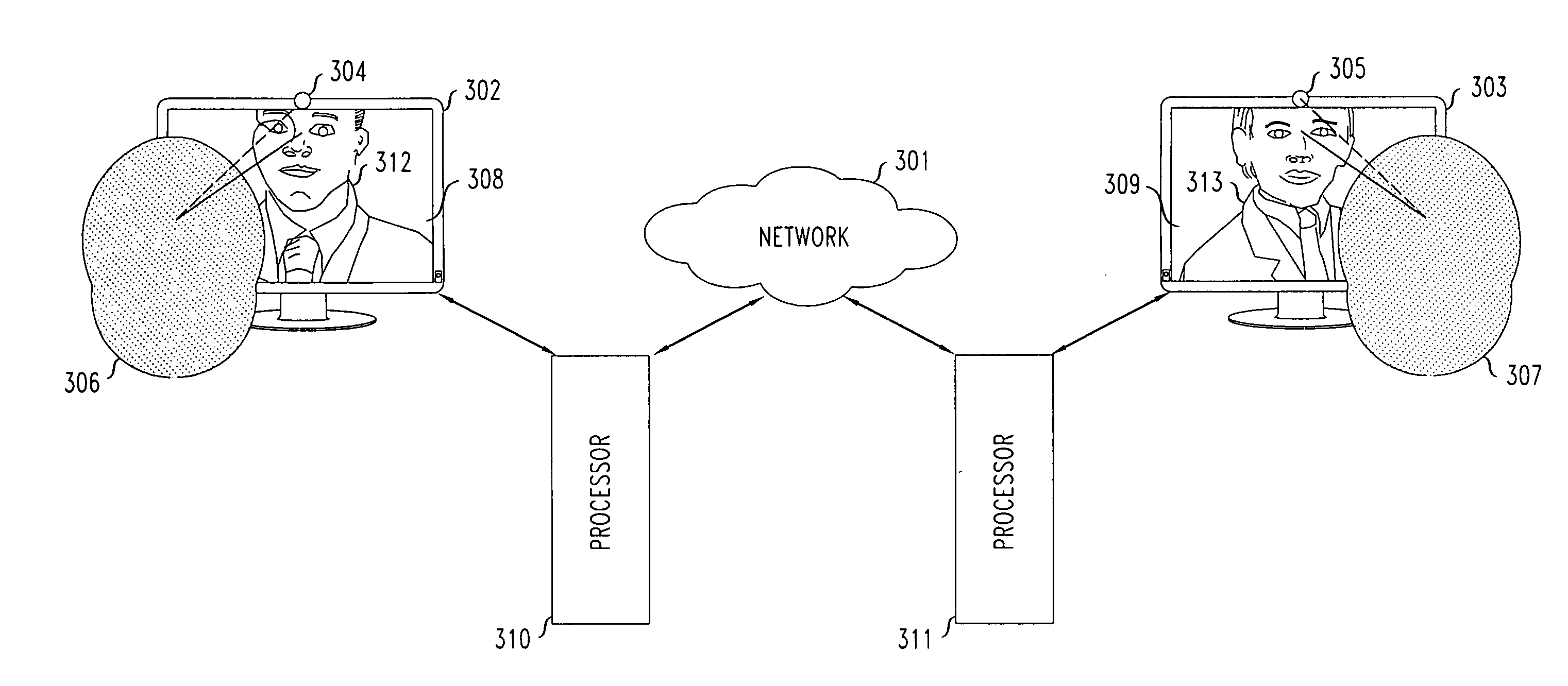
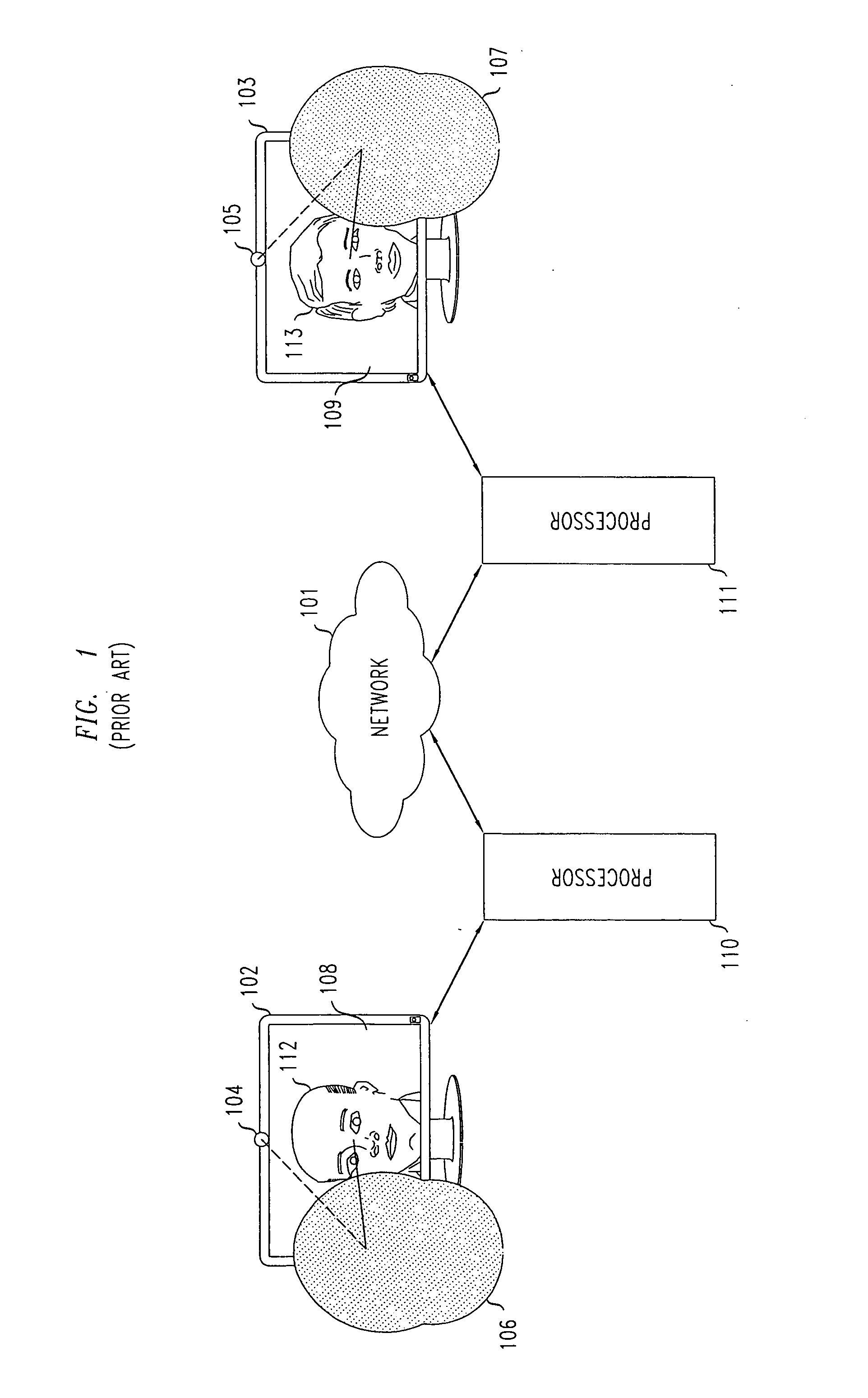
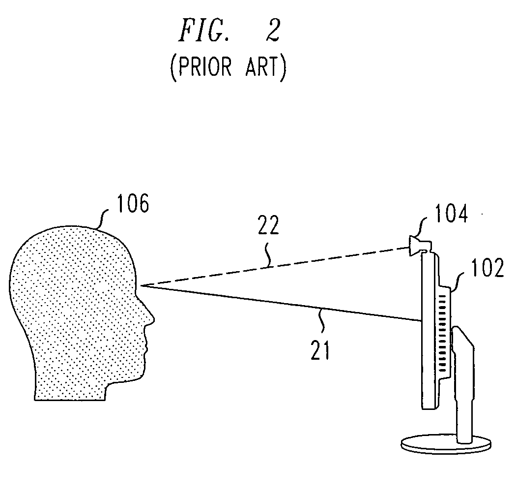
[0020]FIG. 1 shows a prior art video teleconferencing environment which includes two participants who are unable to make reasonable eye contact with each other. The environment shows a video teleconference between two participants—participant 106 and participant 107. Each participant is using a computer-based teleconferencing system including a processor, a monitor with a video screen, and a video camera. As is typical, for each participant, a conventional (i.e., off-the-shelf) video camera is placed on the top of a video monitor (or, equivalently, a laptop screen), in the left-to-right center of the video screen, and is pointed slightly downward to capture one or more images (e.g., a video) of the participant.

[0021]In particular, the computer-based teleconferencing system being used by participant 106 comprises processor 110, video monitor 102 with video screen 108, and video camera 104, while the computer-based teleconferencing system being used by participant 107 comprises proces...


PUM


Abstract

A method and apparatus for displaying images for use during a video teleconference provides improved eye contact between the participants. A video camera mounted on a display (e.g., a monitor or laptop) is co-located with a first participant in the video teleconference. An image of a second participant in the video teleconference is received, and a location of one or more facial features (e.g., the eyes) contained in the image of the second participant is determined. Then, the image of the second participant is displayed on the screen such that the eyes of the second participant are displayed in close proximity to (e.g., directly below) the video camera. In this manner, improved eye contact between the participants is advantageously provided. Alternatively, metadata representing the location of such facial features (e.g., the eyes) contained in the image of the second participant is received along with the image of the second participant.

Description

FIELD OF THE INVENTION[0001]The present invention relates generally to the field of video teleconferencing systems and more particularly to a method and apparatus for enabling improved eye contact for participants thereof.BACKGROUND OF THE INVENTION[0002]Video teleconferencing systems, such as, for example, PC-based systems, are becoming ubiquitous for both business and personal applications. However, such systems do not typically allow for natural eye contact between the participants, because of the angle between the camera, the user, and the video image on the monitor. Most commonly, a camera is placed on top of a monitor or off to its side, but the user is looking squarely into the center of the monitor—disadvantageously, rotated an angle of anywhere from 20 to 70 degrees from the camera lens. This is a broadly acknowledged problem in the video teleconferencing field, and a weakness in essentially all prior art telepresence (e.g., video teleconferencing) systems. In particular, e...

Claims


Application Information

Patent Timeline
IPC IPC(8): H04N7/15
CPCH04N7/144H04N7/15H04N21/4788H04N21/4223H04N21/42203
Inventor MCGOWAN, JAMES WILLIAM
Owner SOUND VIEW INNOVATIONS
Why Eureka
Try Eureka