Lamp assembly including a lamp device detachable from a stand unit for serving as a torch light

a technology of lamp device and lamp assembly, which is applied in the direction of lighting and heating equipment, transportation and packaging, and power sources with built-in, can solve the problems of inability to work, weak battery, and inability to use lamps or lamp assemblies, etc., and achieves convenient manipulation of users, saving costs, and convenient location

Inactive Publication Date: 2010-11-25
ADVANCED CONNECTEK INC
View PDF8 Cites 4 Cited by
  • Summary
  • Abstract
  • Description
  • Claims
  • Application Information

AI Technical Summary

Benefits of technology

[0023]Therefore, the lamp assembly of the present invention is used as table or desktop lamp. In case the lamp device is detached from the stand unit, the same can serve as a torch light or emergency lamp. Due to the storage battery module, no reserved battery is needed or replacement of battery is required. The lamp device does not require specific room for storage in the normal time. In time of power breakdown, the lamp device can be easily located due to its daily use, thereby facilitating the user, which, in turn, saving the expense for buying a conventional torch light for emergency application.
[0024]Due to presence of the rotary structure, the position of the lamp stand with respect to the bottom seat can be adjusted. The On / Off switch is designed ergonomically to facilitate manipulation of the user. The switch device on the lampshade body enables the user to control switch-on or switch-off operation of the light emitting element, when the lamp device is detached from the stand unit.

Problems solved by technology

However, in case of breakdown of electricity, the lamps or lamp assemblies are rendered useless.
Often, even if one can lay hands on the torch light, the torch light may not work since the storage battery may be ruined due to humidity in the atmosphere or due to expiry.
The battery itself becomes weak if it is kept unused for a long period of time.

Method used


Image

  • Lamp assembly including a lamp device detachable from a stand unit for serving as a torch light
  • Lamp assembly including a lamp device detachable from a stand unit for serving as a torch light
  • Lamp assembly including a lamp device detachable from a stand unit for serving as a torch light

Examples


Embodiment Construction

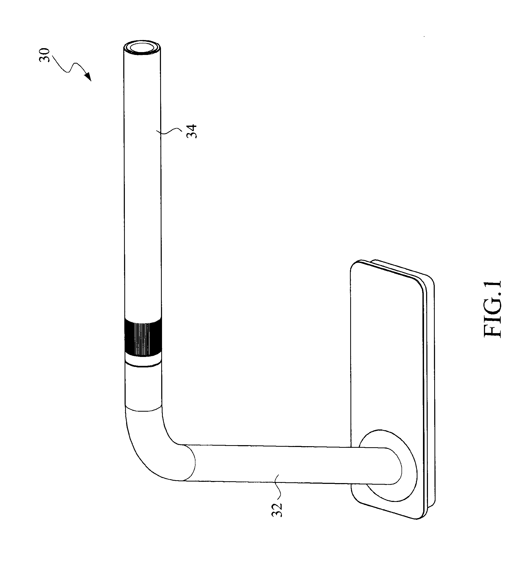
[0035]FIG. 1 is a perspective view of a lamp assembly 30 of the present invention, and includes a stand unit 32 and a lamp device 34. The lamp device 34 is mounted detachably on the stand unit 32. The lamp assembly 30 can be a table lamp or a stand-alone lamp, like the one we dispose at bedside.

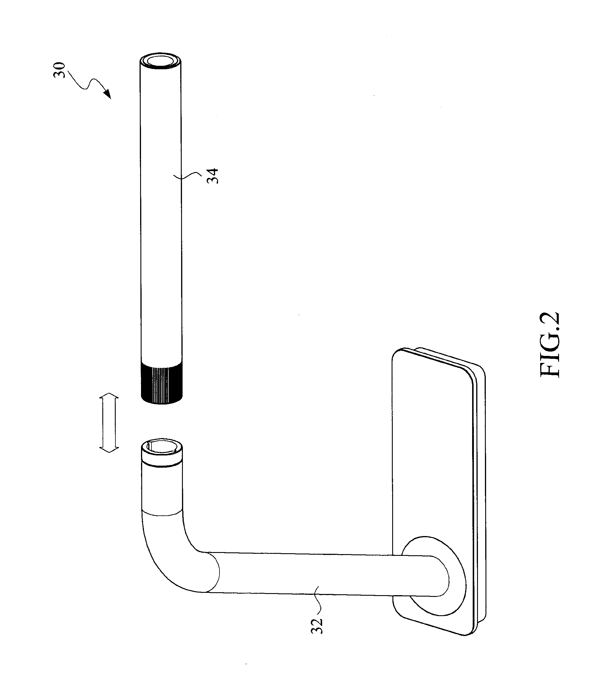
[0036]FIG. 2 is a perspective view of the lamp assembly 30 of the present invention, illustrating the lamp device 34 is detached from the stand unit 32 for independently serving as a torch light or emergency lamp in time of breakout of electricity.

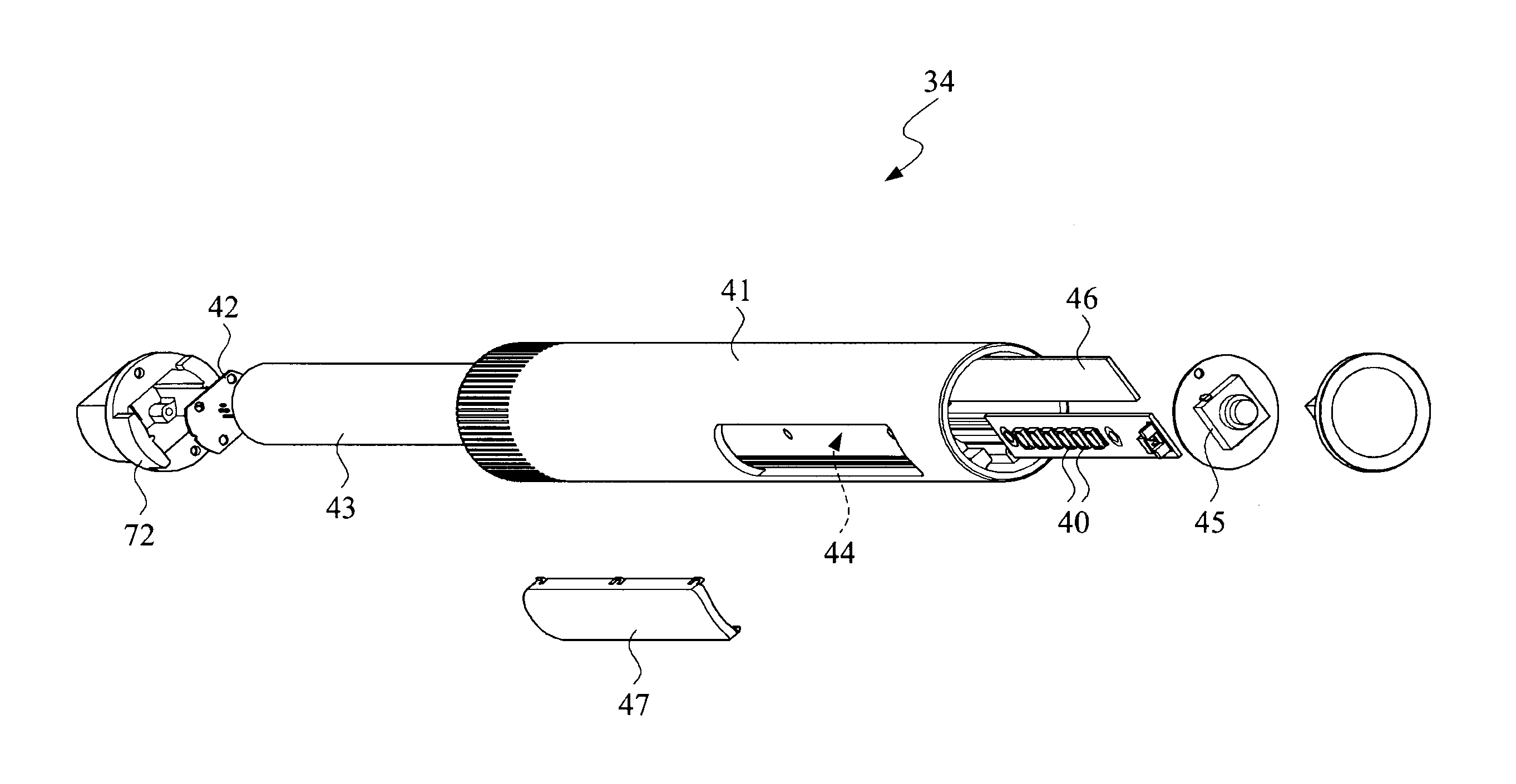
[0037]FIG. 3 is an exploded view of the lamp device employed in the lamp assembly 30 of the present invention. As illustrated, the lamp device 34 includes a light emitting element 40, a lampshade 41, an electrical connector 42 and a storage battery module 43.

[0038]In the present invention, a set of LEDs (Light Emitting Diode) or incandescent bulbs may serve as the light emitting element 40 for emitting light rays. As illustrated, the lampshade 41 in...


PUM


Abstract

A lamp assembly includes a lamp device mounted detachably on a stand unit. The lamp device includes a lampshade for receiving a light emitting element. An electrical connector is coupled electrically to the light emitting element and a power source in such a manner that when the lamp device is mounted on the stand unit, the electrical connector is plugged into the power source so that the light emitting element is supplied with electricity by the power source. A storage battery module is coupled electrically to the electrical connector and the light emitting element so that when the lamp device is mounted on the stand unit, the storage battery module is charged by the power source via the electrical connector. When the lamp device is detached from the stand unit, the light emitting element is supplied with electricity by the storage battery module.

Description

[0001]This application claims the benefits of the Taiwan Patent Application Serial No. 098117009, filed on May 22, 2009, the subject matter of which is incorporated herein by reference.BACKGROUND OF THE INVENTION[0002]1. Field of the Invention[0003]The present invention relates to a lamp assembly, more particularly to a lamp assembly including a stand unit and a lamp device mounted detachably on the stand unit. The lamp device is detachable from the stand unit and is adapted to be served a torch light.[0004]2. Description of the Prior Art[0005]A lamp assembly plays an important role in our daily life. For instance, desktop lamp or table lamp we usually used at home or office generally provides light rays in order to illuminate the drawing room so as to turn the environment into high standard of living.[0006]Most of the aforesaid lamps or lamp assemblies generally rely on A / C power since the latter is easily available at homes and offices and is the cheapest in cost presently. Howeve...

Claims


Application Information

Patent Timeline
Patent Type & Authority Applications(United States)
IPC IPC(8): F21L4/00
CPCF21L4/085F21L13/00F21S9/04F21S9/022F21S6/003F21S13/12F21V17/10
Inventor CHIEN, WEN-HSIANG
Owner ADVANCED CONNECTEK INC
Why Eureka
Try Eureka