Mobile Communication Repeating Method in Moving Object and Repeater Thereof

a technology of moving objects and repeaters, applied in the field of mobile communication repeating technology, can solve the problems of increasing affecting the overall system quality, and high probability of call disconnections, so as to reduce the number of handoffs, reduce the number of redundancy allocation of communication channels, and maintain the signal strength of the serving btss

Inactive Publication Date: 2010-11-25
KMW INC
View PDF10 Cites 48 Cited by
  • Summary
  • Abstract
  • Description
  • Claims
  • Application Information

AI Technical Summary

Benefits of technology

[0018]As described above, the mobile communication repeating method in a moving object according to the present invention steers repeater antennas installed in the moving object to serving BTSs or the best reception directions to receive signals from the serving BTSs according to a plurality of service providers or selects antennas that are steered to the serving BTSs or the best reception directions to receive signal

Problems solved by technology

Due to natural or artificial topographical obstacles, a communication shadowing area exists in which an MS cannot receive a signal from a BTS reliably.
Particularly when there area many topographical objects near the MS or the MS moves often, a severe multi-path fading results, increasing a

Method used


Image

  • Mobile Communication Repeating Method in Moving Object and Repeater Thereof
  • Mobile Communication Repeating Method in Moving Object and Repeater Thereof
  • Mobile Communication Repeating Method in Moving Object and Repeater Thereof

Examples


embodiment 1

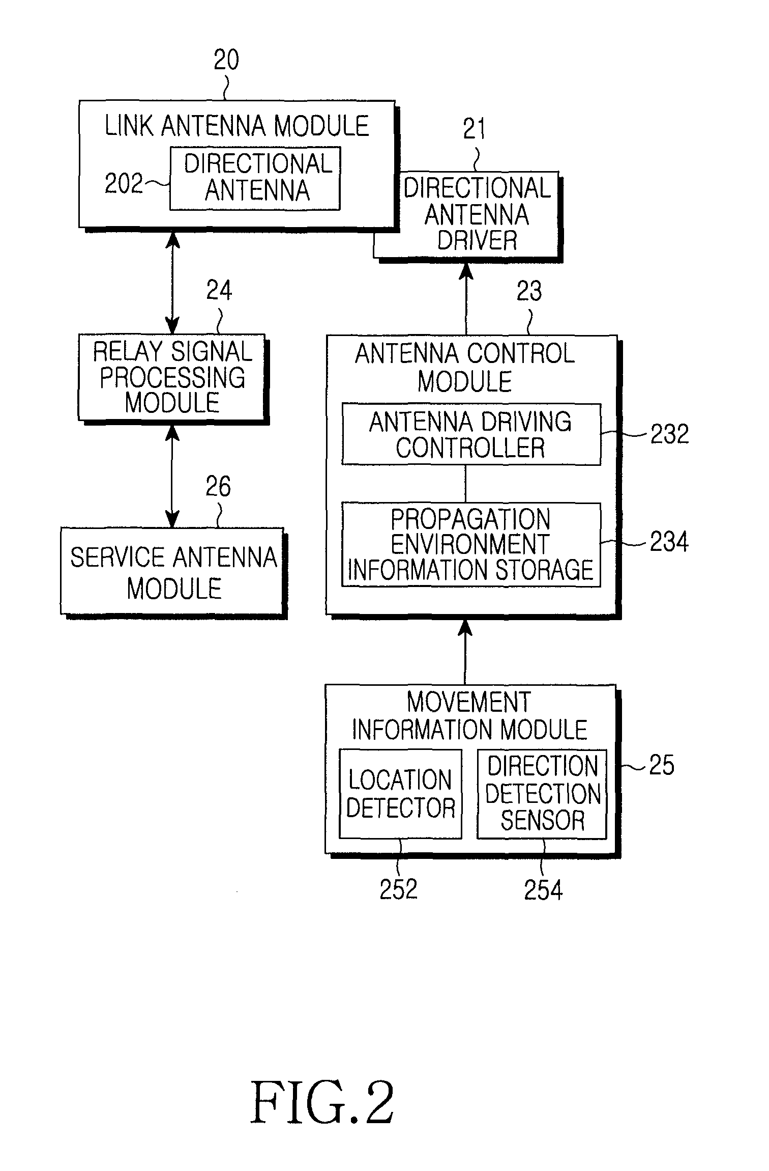
[0033]FIG. 2 is a block diagram of a repeater installed in a moving object according to an embodiment of the present invention. Referring to FIG. 2, the repeater according to the embodiment of the present invention basically includes a link antenna module 20 for wireless communication with a BTS. The link antenna module 20 may includes at least one rotating directional antenna 202 for rotating mechanically or electrically, of which the direction can be controlled by a driver (directional antenna driver) 21.

[0034]The repeater further includes a relay signal processing module 24 for performing a typical wireless communication repeating operation. The relay signal processing module 24 filters and amplifies a signal received from the link antenna module to thereby compensate the signal to be receivable at an MS. The relay signal processing module 24 also filters and amplifies a signal received from an MS and outputs the amplified signal to a BTS through the link antenna module 20.

[0035]...

embodiment 2

[0043]FIG. 3 is a block diagram of a repeater installed in a moving object according to another embodiment of the present invention. Referring to FIG. 3, like the first embodiment of the present invention illustrated in FIG. 2, the repeater according to the second embodiment of the present invention includes a link antenna module 30 for wireless communication with a BTS, the relay signal processing module 24 for performing a typical wireless communication repetition operation, and the service antenna module 26 for wirelessly communicating with MSs within a moving object.

[0044]The link antenna module 30 may have a plurality of fixed antennas ANT1, ANT2, . . . , ANTN, compared to the first embodiment of the present invention illustrated in FIG. 2. For example, the link antenna module 30 can have four fixed antennas and be installed in the directions of East, West, South and North. Or the link antenna module 30 may have more antennas and be installed in more directions.

[0045]The repeat...

embodiment 3

[0050]FIG. 4 is a block diagram of a repeater installed in a moving object according to a third embodiment of the present invention. Referring to FIG. 4, like the second embodiment of the present invention illustrated in FIG. 3, the repeater according to the third embodiment of the present invention includes the link antenna module 30 for wireless communication with a BTS, the relay signal processing module 24 for performing a typical wireless communication repetition operation, and the service antenna module 26 for wirelessly communicating with MSs within the moving object.

[0051]As in the second embodiment of the present invention, the link antenna module 30 may have a plurality of fixed antennas ANT1, ANT2, . . . , ANTN and the repeater further includes the link antenna path setting module 32 for selecting at least one of the fixed antennas ANT1, ANT2, . . . , ANTN and connecting a path between the selected fixed antenna and the following relay signal processing module 24.

[0052]Al...


PUM


Abstract

A repeater installed in a moving object is provided, in which a link antenna module has a plurality of link antennas steered to predetermined directions, for wirelessly communicating with a Base Transceiver Station (BTS), a link antenna path setting module selects at least one of the plurality of link antennas of the link antenna module and connects a path between the selected link antenna and a rear end, a service antenna module has at least one service antenna installed within the moving object, for wirelessly communicating with Mobile Stations (MSs) within the moving object, a relay signal processing module is connected to the link antenna module through the link antenna path setting module and processes transmission and reception relay signals between the link antenna module and the service antenna module, a movement information module measures current movement information about the moving object and provides the current movement information, a received signal measuring module measures a received signal of the link antenna module and providing current propagation environment information, and an antenna control module detects a current movement state and a current propagation environment based on the information received from the received signal measuring module and the movement information module, stores and/or updates the information in an internal propagation environment information storage, and controls the link antenna path setting module to select a link antenna that receives the best signal from a serving BTS at each location according to the stored information.

Description

BACKGROUND OF THE INVENTION[0001]1. Field of the Invention[0002]The present invention generally relates to a mobile communication repeating technology in a cellular mobile communication network. More particularly, the present invention relates to a repeater mounted to a moving object such as a bus, a vehicle, a train, a subway, and a ship and a wireless communication repeating method.[0003]2. Description of the Related Art[0004]In general, a cellular mobile communication network includes a Mobile Switching Center (MSC), a Base Station Controller (BSC), a Base Transceiver Station (BTS), and a Mobile Station (MS). It expands service coverage by installing multiple BTSs. Due to natural or artificial topographical obstacles, a communication shadowing area exists in which an MS cannot receive a signal from a BTS reliably. To relay signals between the BTS and the MS, a wired or wireless repeater is installed in the communication shadowing area. Especially some wireless repeaters are mount...

Claims


Application Information

Patent Timeline
IPC IPC(8): H04B7/15
CPCH04B7/1555
Inventor KIM, DUK-YONG
Owner KMW INC
Why Eureka
Try Eureka