
Non-Negative Matrix Factorization as a Feature Selection Tool for Maximum Margin Classifiers

a feature selection and feature selection technology, applied in the field of identifying a maximum margin classifier, can solve the problems of not providing an optimal separation between the first and second data clusters, and not providing useful information regarding similarities

Inactive Publication Date: 2010-11-25
SEIKO EPSON CORP
View PDF6 Cites 10 Cited by
  • Summary
  • Abstract
  • Description
  • Claims
  • Application Information

AI Technical Summary

Benefits of technology

[0023]Preferably, the present objects are achieved by decomposing a given matrix vector X into two matrix vectors, F and G. This decomposing process includes minimizing a cost function that combine a non-negative matrix factorization, NMF and maximum margin classifier satisfying the following relationship:minF,G≥0X-FG2+γ(w2+C∑i=1nL(yi,w·gi+b))wherein: X∈; F∈; G∈; w∈; yi∈{−1,1}∀i; gi∈ is the ith column of G; symbol (.) represents the dot product of the two vectors; L(y,t) is a loss function where t=(w·gi+b), and L(y,t)=max(0, 1−yt)p and γ is a constant that distributes the relative importance of the two terms in the optimization.
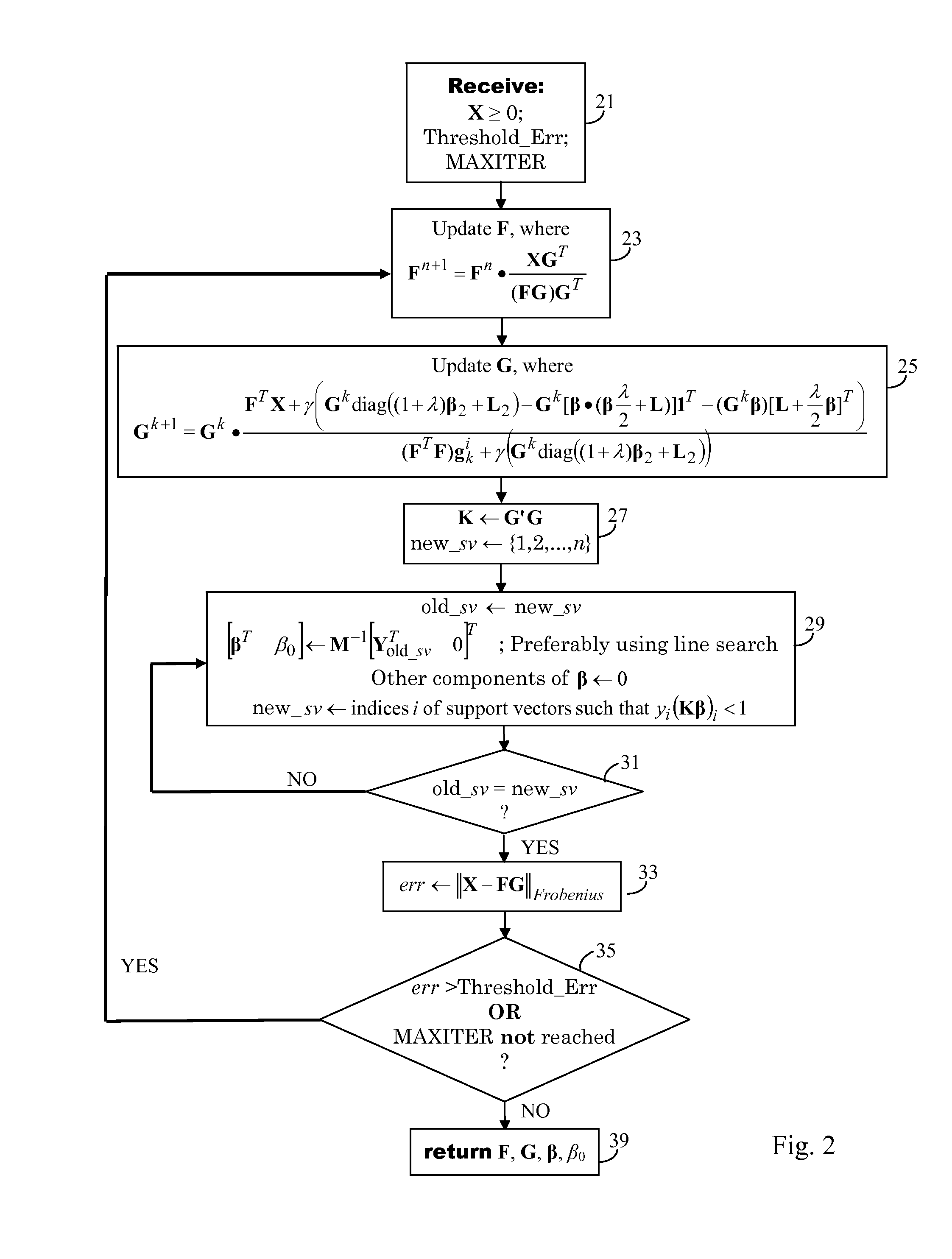
[0024]In this approach, minimizing the cost function is achieved by successive iterations, and γ is the relative weighting between the generative component and the discriminative component of the cost function, and γ is increased incrementally from 0 to 1 during each iteration. Preferably during each iteration, F is updated by the following relationship:Fn+1=Fn·XGT(FG)GT.

Problems solved by technology

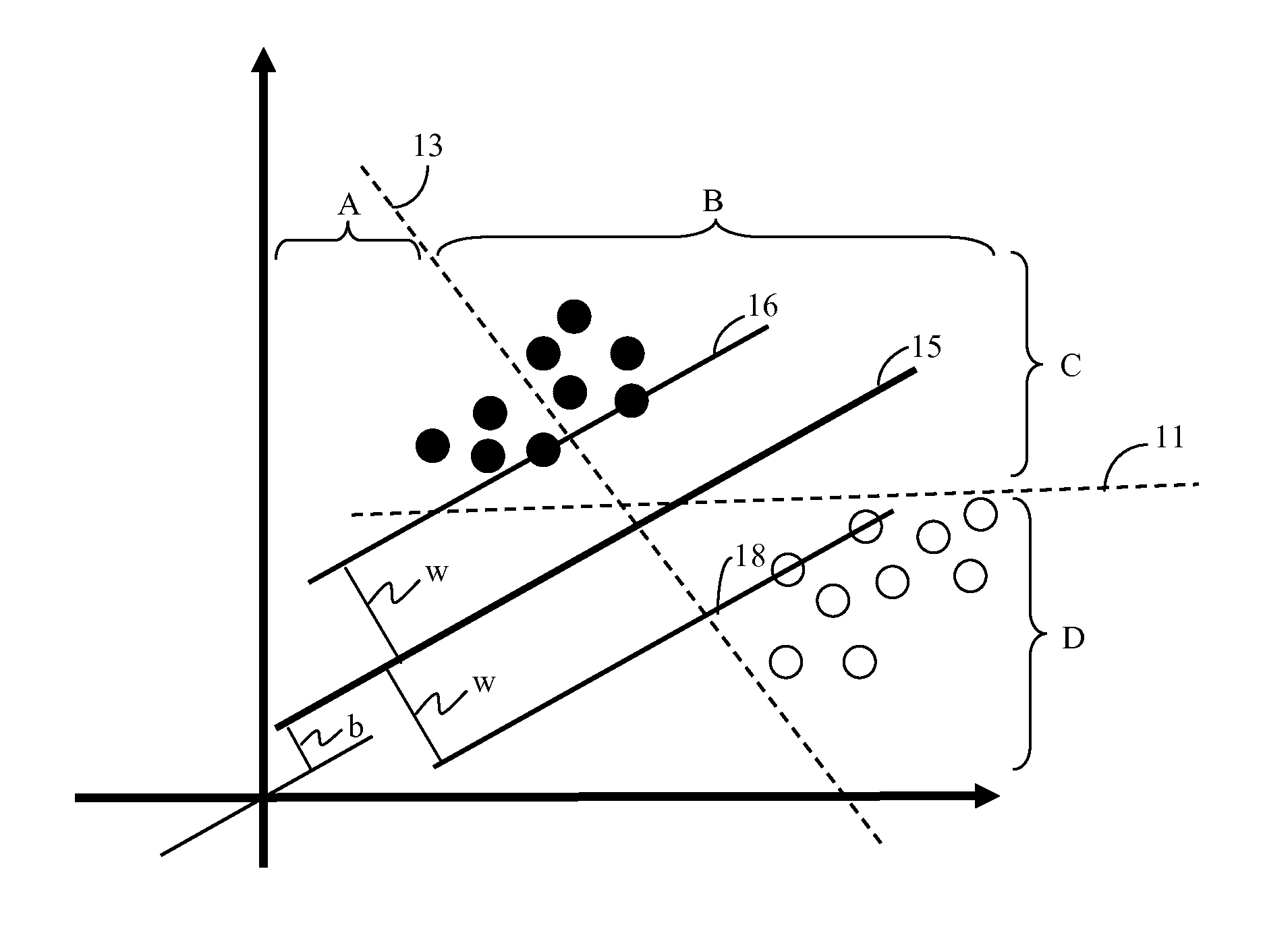
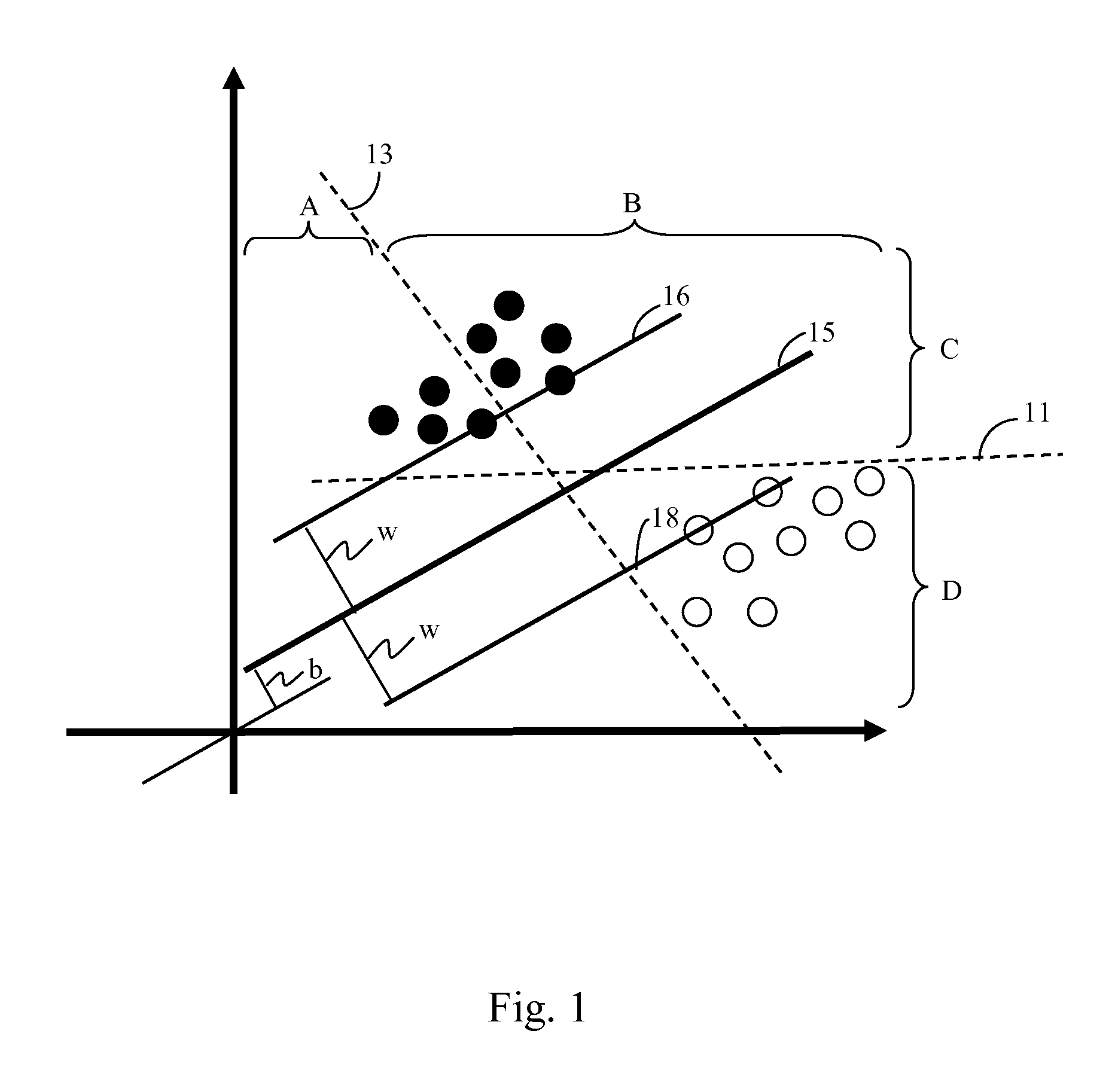
In the present case, it is relatively self-apparent that hyperplane 13 does not provide useful information regarding similarities or differences between the data points since it does not accurately differentiate between the two data clusters.
Hyperplane 11 does separate the first data cluster (consisting of nine darkened data points) on its upper side (side C) from the second data cluster (consisting of nine lightened data points) on its lower side (side D), but does not provide an optimal separation between the first and second data clusters.

Method used


Image

  • Non-Negative Matrix Factorization as a Feature Selection Tool for Maximum Margin Classifiers
  • Non-Negative Matrix Factorization as a Feature Selection Tool for Maximum Margin Classifiers
  • Non-Negative Matrix Factorization as a Feature Selection Tool for Maximum Margin Classifiers

Examples


Embodiment Construction

[0044]Various extensions and variations of non-negative matrix factorization (NMF) have been proposed, but NMF, in a general form, can be described by the following factorization:

Xd×N=Wd×rHr×N  (1)

where d is the dimension of the data, N is the number of data points (usually more than d) and r<d. Generally, this factorization has been compared with data decomposition techniques. In this sense W is called the set of basis functions and the set H is the data specific weights. It has been claimed by some researchers that such a decomposition has some favorable properties over other similar decompositions, such as PCA etc.

[0045]Most of the work in this field, to date, has dealt with NMF decomposition as a unary operation. Penalties such as sparseness constraint, have been proposed, but the motivation still remains largely experimental. A non-smooth NMF that distributes the sparseness constraint to both the basis as well as feature matrices has also been proposed. More recently, a graph l...


PUM


Abstract

Non-negative matrix factorization, NMF, is combined with identification of a maximum margin classifier by minimizing a cost function that contains a generative component and the discriminative component. The relative weighting between the generative component and the discriminative component are adjusting during subsequent iterations such that initially, when confidence is low, the generative model is favored. But as the iterations proceed, confidence increases and the weight of the discriminative component is steadily increased until it is of equal weight as the generative model. Preferably, the cost function to be minimized is:minF,G≥0X-FG2+γ(w2+C∑i=1nL(yi,w·gi+b)).

Description

CONTINUING APPLICATION DATA[0001]This application claims the benefit of U.S. Provisional Application No. 61 / 179,854 filed May 20, 2009 under 35 U.S.C. §119(e) and is hereby incorporated by reference in its entirety.BACKGROUND[0002]1. Field of Invention[0003]The present invention relates to the field of identifying a maximum margin classifier for classification of data, and is specifically directed to a method of optimizing the identifying of such a maximum margin classifier when analyzing a large set of data points.[0004]2. Description of Related Art[0005]Non-negative matrix factorization (NMF) is generally a group of algorithms in multivariate analysis (i.e. having more than one variable) and linear algebra where a matrix, X, is factorized into (usually) two matrices, W and H such that NMF (X)→WH.[0006]Non-negative matrix factorization (NMF) has been shown to be a useful decomposition for multivariate data, and NMF permits additive combinations of non-negative basis components.[000...

Claims


Application Information

Patent Timeline
Patent Type & Authority Applications(United States)
IPC IPC(8): G06F17/11G06F17/16
CPCG06F17/16G06N20/10G06F18/2411
Inventor DAS GUPTA, MITHUNXIAO, JING
Owner SEIKO EPSON CORP
Learn More