Vibration actuator and electric device

a technology of vibration actuator and electric device, which is applied in the direction of piezoelectric/electrostrictive/magnetostrictive devices, piezoelectric/electrostriction/magnetostriction machines, gearing, etc., can solve the problems of increasing weight and high cost, and achieve the effect of favorable characteristics

Active Publication Date: 2010-12-02
NIKON CORP
View PDF9 Cites 3 Cited by
  • Summary
  • Abstract
  • Description
  • Claims
  • Application Information

AI Technical Summary

Benefits of technology

[0006]However, when using metal as the bearing material, the cost becomes high, and the weight increases.
[0023]According to the present invention, it is possible to provide a vibration actuator and electric device having favorable characteristics.

Problems solved by technology

However, when using metal as the bearing material, the cost becomes high, and the weight increases.

Method used


Image

  • Vibration actuator and electric device
  • Vibration actuator and electric device
  • Vibration actuator and electric device

Examples


first embodiment

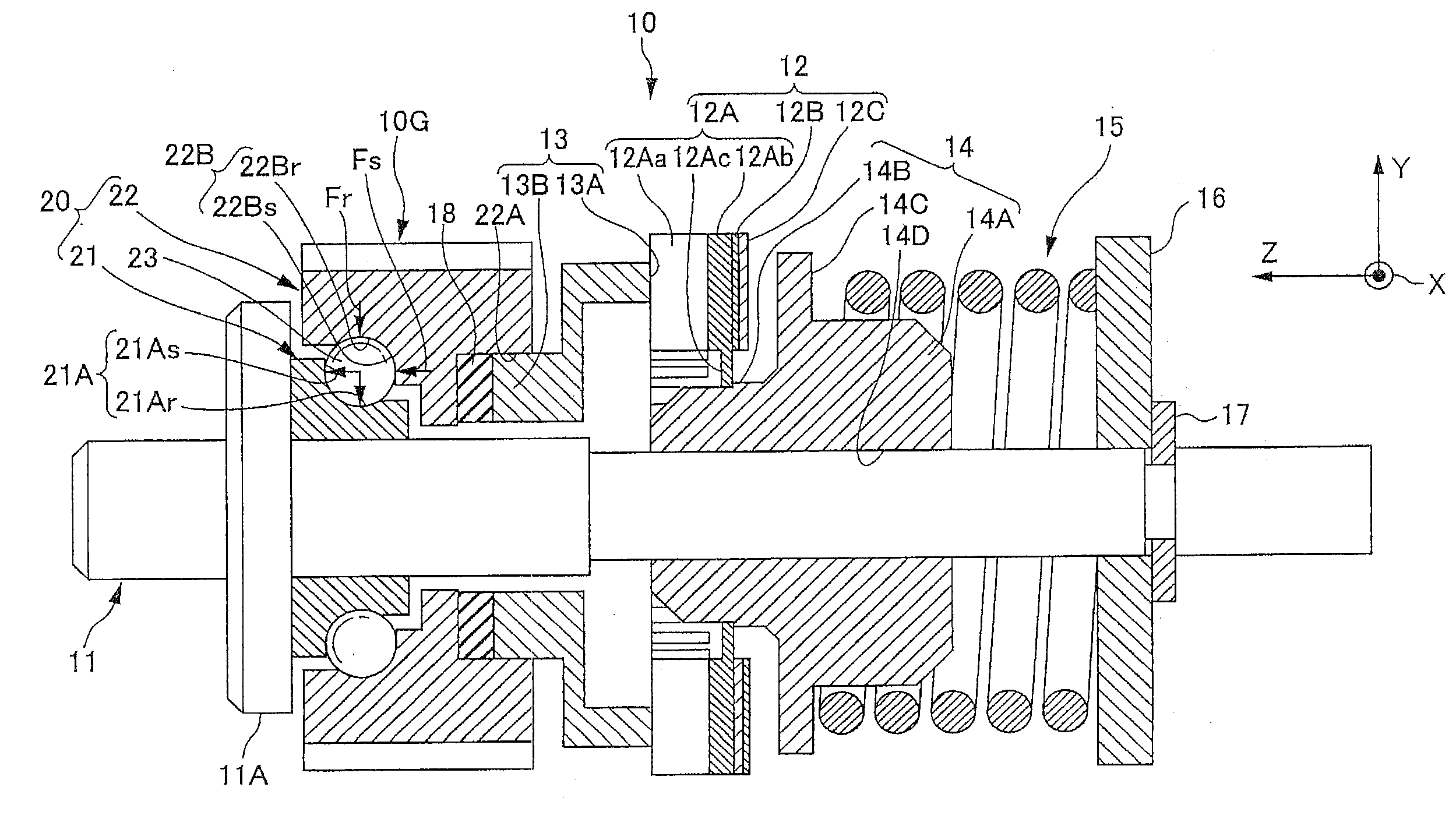
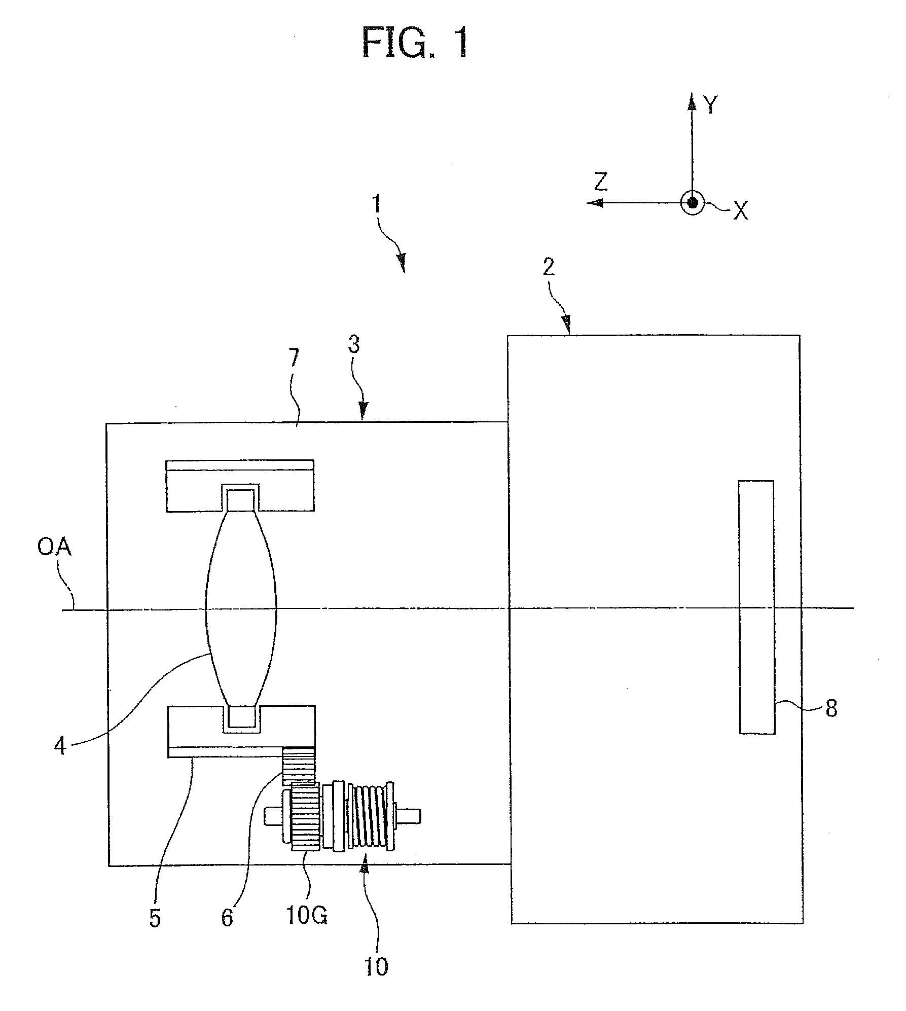
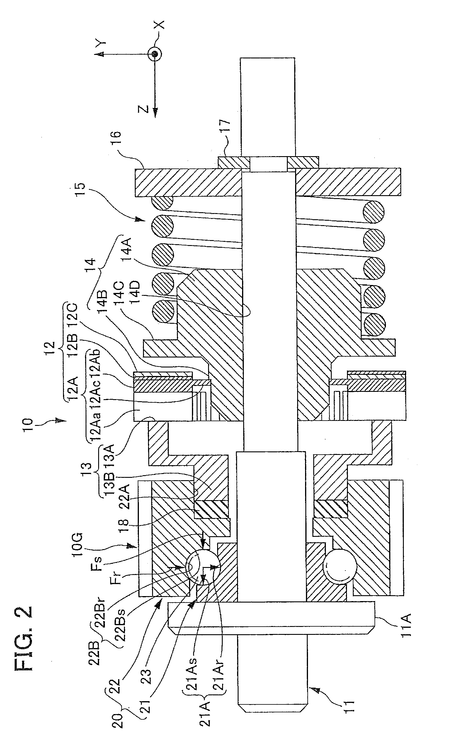
[0029]Below, the first embodiment of the present invention will be explained with reference to the drawings and the like. Further, in each of the following drawings, in order to facilitate the explanations and understanding, an XYZ Cartesian coordinate system is established. In this coordinate system, in the position of the camera when photographing an image in the landscape orientation with the photographer making the optical axis A horizontal (below referred to as the normal position), the direction towards the left side as seen by the photographer is the X-plus direction. Further, in the normal position, the upwards direction is the Y-plus direction. Furthermore, in the normal position, the direction towards the subject is the 1-plus direction.

[0030]FIG. 1 is a conceptual drawing explaining the camera 1 of the first embodiment. In the camera 1 of the first embodiment, an ultrasonic motor 10 is provided as an example of the vibration actuator.

[0031]The camera 1 is provided with a ...

second embodiment

[0087]Next, the second embodiment of the present invention will be explained with reference to FIG. 3 and FIG. 4.

[0088]FIG. 3 is a cross sectional drawing of the ultrasonic motor 110 according to the second embodiment. FIG. 4 is a an enlarged drawing of a portion of the bearing 120 of FIG. 3.

[0089]The ultrasonic motor 110 shown in FIG. 3, in the same way as in the first embodiment, is used for an application such as the rotational driving of a cam tube 5 of a lens barrel 3, but in the present embodiment it is constituted in a ring shape.

[0090]Further, the bearing 120 in the ultrasonic motor 110 of the present embodiment is constituted in approximately the same way as the bearing 20 in the previously described first embodiment, and detailed explanations of identical constituent elements are omitted.

[0091]The ultrasonic motor 110 is provided with a support ring 111, an vibrating element 112, a rotating body 113, a bearing 120, a pressing portion 115, and a fixing ring 116. Further, th...

third embodiment

[0116]Below, the third embodiment of the present invention will be described with reference to the drawings. FIG. 5 is a longitudinal (axial direction) cross section drawing of the ultrasonic motor 210 of the third embodiment.

[0117]The third embodiment is approximately the same as the second embodiment, but differs in the point that the balls 123 are held by the retainer 125. The other parts are the same as for the second embodiment, and thus are assigned the same reference numbers, and explanations thereof are omitted.

[0118]The retainer 125 is an annular member extending along the entire circumference of the gap between the inner wheel 121 and the outer wheel 122. Further, as shown in FIG. 5, in the retainer 125, a cross section parallel to the central axis of the retainer 125 is inclined by a prescribed angle with respect to this central axis. Namely, the retainer 125 has a shape wherein a part of the side face of a cone has been cut out to a predetermined width. The side face of ...


PUM


Abstract

A vibration actuator comprising: a vibration portion which contacts a relative movement portion, and produces necessary vibration for a relative movement of the relative movement portion; a first member provided to hold the relative movement portion between the first member and the vibration portion, and moves relative to the vibration portion in response to movement of the relative movement portion with respect to the vibration portion; a second member which faces the first member via a rolling member, and supports the first member so that the first member is movable relative to the vibration portion; and a pressing member which generate a pressing force between the second member and the vibration portion so that the vibration portion and the relative movement portion are in contact with each othercome in contact with each other; and wherein the first member comprises a plastic substance.

Description

[0001]The present application claims priority under 35 U.S.C. §119 to Japanese Patent Applications No. 2009-126126 filed on May 26, 2009, and No. 2010-117169 filed on May 21, 2010. The content of the application is incorporated herein by reference in its entirety.BACKGROUND OF THE INVENTION[0002]1. Field of the Invention[0003]The present invention relates to a vibration actuator and an electric device.[0004]2. Description of the Related Art[0005]There has been a vibration actuator wherein an vibrating element is made to vibrate using an electromechanical conversion element, and a moving element is made to rotate by these vibrations. In such an vibration actuator, a bearing is used in order to hold the moving element so as to be rotatable with respect to the vibrating element (for example, refer to Japanese Unexamined Patent Publication No. Hei 10-319300). Thus far, metal has been used as the material for this bearing.SUMMARY OF THE INVENTION[0006]However, when using metal as the bea...

Claims


Application Information

Patent Timeline
Patent Type & Authority Applications(United States)
IPC IPC(8): F16H21/52F16H21/46
CPCH02N2/163Y10T74/18856Y10T74/18056
Inventor HINO, MITSUTERU
Owner NIKON CORP
Why Eureka
Try Eureka